
Cycloidal lantern gear reducer

A technology of cycloidal pinwheel deceleration and pintooth housing, which is applied in the direction of mechanical equipment, gear transmission, belt/chain/gear, etc., to achieve the effects of small size, solving sliding problems, and reducing costs

Inactive Publication Date: 2010-04-28
QUANTA MACHINERY CO LTD
View PDF0 Cites 9 Cited by
  • Summary
  • Abstract
  • Description
  • Claims
  • Application Information

AI Technical Summary

Problems solved by technology

Although some end support bearings design the cylindrical rollers distributed along the radial circumference into a drum shape, and the middle of the rollers is slightly larger than the two ends, so as to minimize the sliding process of the rollers, but it cannot avoid sliding

Method used


Image

  • Cycloidal lantern gear reducer
  • Cycloidal lantern gear reducer
  • Cycloidal lantern gear reducer

Examples


Embodiment Construction

[0020] The specific structure of the present invention will be further described below in conjunction with the accompanying drawings.

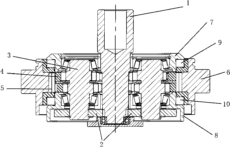
[0021] Such as figure 1 Shown is a cycloidal pinwheel reducer, the input shaft 1 of the cycloidal pinwheel reducer is connected to the motor, the end of the input shaft 1 has a ring tooth structure, and the tooth shape on the input shaft 1 is fixed on the crankshaft 3 The two ends of the crankshaft 3 are respectively supported on the gland 7 and the output disk 8. There are two eccentric parts on the crankshaft 3. The positions of the two eccentric parts are opposite to each other at 180°. The two eccentric parts are respectively installed on the cycloidal disk. In the hole on 4, the cycloidal disc 4 meshes with the needle roller 5 fixed on the pin tooth housing 6 through the teeth on its circumference, and the cycloidal disc 4 is connected with the gland 7 and the output disc 8 by screws to rotate together For output, a rolling bearing 9 is ...


PUM


Abstract

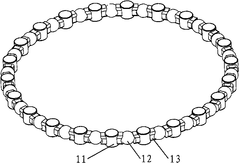
The invention relates to a cycloidal lantern gear reducer. A rolling bearing is arranged between an output disc and a pin gear housing of the cycloidal lantern gear reducer and comprises a bearing inner ring, a bearing outer ring and a rolling body clamped between the bearing inner ring and the bearing outer ring, wherein the rolling body comprises a plurality of cylindrical rollers and spherical rollers; the cylindrical rollers and the spherical rollers are arranged along the same circumference alternately; retaining frames are arranged between adjacent cylindrical rollers and spherical rollers; the shaft axes of the cylindrical rollers are parallel to the shaft axes of the shaft axis of the bearing; the diameter of the spherical rollers is smaller than that of the cylindrical rollers; and the diameter of the spherical rollers is greater than the height of the cylindrical rollers. The cycloidal lantern gear reducer of the invention is compact, small in volume and low in cost.

Description

technical field [0001] The invention relates to a cycloidal pinwheel reducer. Background technique [0002] Most of the domestic cycloid reducers are large in size, low in transmission accuracy, and large in hysteresis, and generally can only be used in equipment with low requirements, such as metallurgical and mining machinery, lifting equipment, etc. One of the influencing factors is that the end support bearings used in the cycloid reducer are difficult to meet the actual needs. There are two types of end support bearings on common miniaturized cycloid reducers: [0003] One is the angular contact ball bearing, which can be changed to a non-standard thin-walled bearing in order to reduce the volume, and the inner ring of the angular contact ball bearing is removed for the reducer with a smaller volume, and the roller table is directly used as the gland and the output on the plate. However, through the transformation of the above structure, the bearing has become a non-...

Claims


Application Information

Patent Timeline
Patent Type & Authority Applications(China)
IPC IPC(8): F16H1/20F16C19/49
Inventor 曾铭淇彭学云柯翔
Owner QUANTA MACHINERY CO LTD
Learn More