Rotor rubbing test device

An experimental device and rubbing technology, applied in the direction of educational appliances, instruments, teaching models, etc., can solve the problems of easily damaged shafts, which have not been well solved, and the simulation of rotating and static bumping faults is large, so as to achieve easy replacement and avoid damage Effect

Inactive Publication Date: 2010-04-28
NANJING UNIV OF AERONAUTICS & ASTRONAUTICS
View PDF0 Cites 14 Cited by
  • Summary
  • Abstract
  • Description
  • Claims
  • Application Information

AI Technical Summary

Problems solved by technology

[0002] At present, the rotor test bench is commonly used in laboratories to simulate various operating states of rotating machinery, but the simulation of rotational and static collision faults has always been a big problem, and has not been well resolved for a long time
The existing rubbing device is mainly composed of friction screws and a bracket fastened on the test bench. It mainly realizes rubbing faults by adjusting the distance between the bolt and the rotating shaft. However, in the process of rubbing experiments, the bolt- Rotor contact (i.e., point contact) rubbing is the main method, which is inconsistent with most actual rotor and stator rubbing situations. It can only simulate single-point rubbing. Rubbing is powerless, and such rubbing is easy to damage the shaft, and rubbing experiments can only be carried out in a short time.
Therefore, the existing friction rubbing experiment device of the rotor test bench is difficult to meet the teaching and scientific research requirements of the rubbing rubbing experiment in the laboratory

Method used


Image

  • Rotor rubbing test device
  • Rotor rubbing test device
  • Rotor rubbing test device

Examples


Embodiment Construction

[0014] Below in conjunction with accompanying drawing and specific embodiment the present invention is described in further detail:

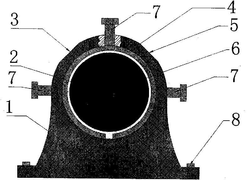
[0015] exist figure 1 In the front view of the rubbing device of the present invention, it mainly includes a support (1), a stator snap ring (4), a rotating member (6), a rubbing bolt (7) and a fastening bolt (8). The device is fixed on the test bench by fastening bolts (8) on the support (1), and is operated together with other components on the test bench to complete the experiment.

[0016] In the device, the rotating member (6) is connected with the rotating shaft (2) in an interference fit manner. It can be a disc or other rotating parts such as a turbine or impeller and is very easy to replace.

[0017] Stator snap ring 4 adopts copper material to make, and it is non-full circumference, but has the slit of certain width, is clearance fit between it and the rotating part, and its internal diameter is slightly larger than rotating part out...


PUM


Abstract

The invention relates to a rotor rubbing test device, belonging to the technical field of a rotor fault test simulating device. The rotor rubbing test device is characterized by mainly comprising a supporting seat (1) with a circular test channel, wherein a stator clamping ring (4) is also installed in the circular test channel; the stator clamping ring (4) is in an incomplete circumference shape and has gaps; a rotating piece (6) is fixed on a rotating shaft (2) and is positioned inside the stator clamping ring (4), and an interval exists between the rotating piece (6) and the stator clamping ring (4); 2-4 rubbing bolts (7) are installed on the supporting seat (1) in the position of the circular test channel; and when the rubbing bolts (7) are screwed, the stator clamping ring (4) is in contact with the rotating piece (6). The rotor rubbing test device prevents the rotating shaft from being damaged and simulates the real rubbing state.

Description

technical field [0001] The rotor rubbing test device of the present invention relates to an accessory on a universal rotor test bench, and is a rotor fault experiment simulation device. More specifically, the present invention is for simulating a rotor rubbing fault experiment on a universal rotor test bench, providing A more realistic and fully functional experimental setup. Background technique [0002] At present, the rotor test bench is commonly used in laboratories to simulate various operating states of rotating machinery, but the simulation of rotational and static collision faults has always been a big problem, and has not been well resolved for a long time. The existing rubbing device is mainly composed of friction screws and a bracket fastened on the test bench. It mainly realizes rubbing faults by adjusting the distance between the bolt and the rotating shaft. However, in the process of rubbing experiments, the bolt- Rotor contact (i.e., point contact) rubbing is...

Claims


Application Information

Patent Timeline
Patent Type & Authority Applications(China)
IPC IPC(8): G09B25/02
Inventor 乔保栋陈果曲秀秀
Owner NANJING UNIV OF AERONAUTICS & ASTRONAUTICS
Why Eureka
Try Eureka