
Female joint of coaxial cable connector

A coaxial cable and connector technology, applied in the direction of conductive connection, connection, two-part connection device, etc., can solve the problems of not being able to produce in batches, not easy to control, and difficult to realize welding, etc., to achieve good versatility, convenient assembly, and reduce vibration The effect of displacement

Active Publication Date: 2010-04-28
ROSENBERGER ASIA PACIFIC ELECTRONIC CO LTD
View PDF1 Cites 7 Cited by
  • Summary
  • Abstract
  • Description
  • Claims
  • Application Information

AI Technical Summary

Problems solved by technology

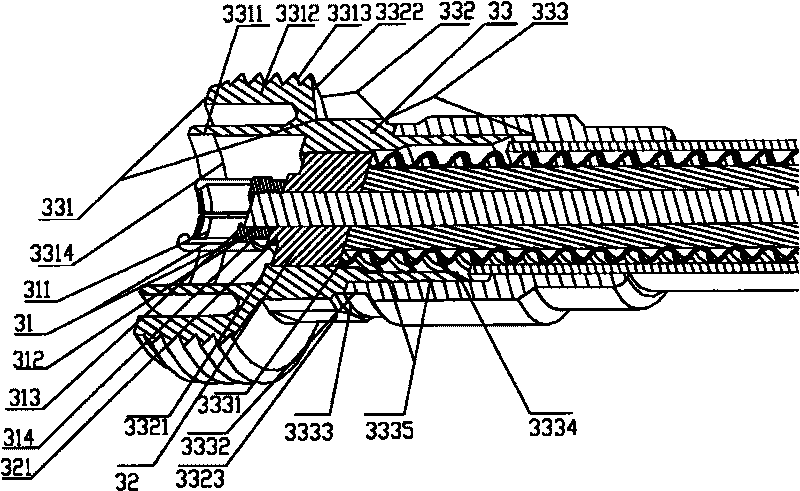
[0011] However, in use, the inventor found that the center conductor 31 of the improved female joint is only fixed by the center conductor of the coaxial cable inserted therein, and needs to be welded
However, welding is difficult to achieve, and the heating operation is complicated and the coaxiality between the central conductor and the outer conductor is difficult to ensure, so the electrical performance fluctuates, is difficult to control, and cannot be mass-produced. In addition, the central conductor is easily affected by the central conductor of the coaxial cable. The displacement occurs due to the movement, resulting in poor signal transmission

Method used


Image

  • Female joint of coaxial cable connector
  • Female joint of coaxial cable connector
  • Female joint of coaxial cable connector

Examples


Embodiment Construction

[0028] Embodiments of the present invention will be described in detail below in conjunction with the accompanying drawings.

[0029]The following embodiment introduces a male-female mating interface that is applied to a female connector of a 7 / 16-type coaxial cable connector and meets the DIN 47223 standard widely released around the world. However, the basic structural improvements proposed in this embodiment can be widely used in various standard coaxial cable connectors. For the convenience of description, the direction of the plugging interface between the male connector and the female connector is referred to as the front end, and the end where the coaxial cable is terminated is referred to as the rear end.

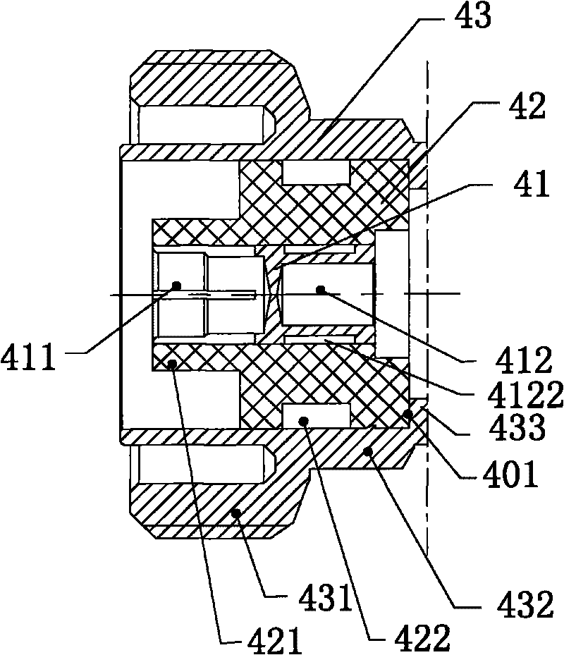
[0030] Such as image 3 As shown, the female joint of the coaxial cable connector according to Embodiment 1 of the present invention has a ring-shaped structure with inner, middle and outer layers. The front part of the central conductor 41 has a concave insertion...


PUM


Abstract

The invention discloses a female joint of a coaxial cable connector, which comprises a central conductor, an insulator and an outer conductor; the central conductor is provided with a concave jack and a deep hole used for inserting an inner conductor of coaxial cable; the insulator is a circular ring with a through hole in the center; the external diameter of the front end part of the insulator is less than the external diameter of the rear end part; the outer conductor is divided into a front section, a middle section and a rear section; the front section is provided with an annular socket facing towards the front end; the internal diameter of the rear section is used for inserting the coaxial cable; the internal diameter of the front section is equal to the internal diameter of the middle section and matched with the external diameter of the rear end part of the insulator; the internal surface of the middle section is transited to the internal surface of the rear section through a first step; the internal diameter of the through hole of the insulator is matched with the external diameter of the concave jack of the central conductor; the central conductor can be integrally inserted into the through hole of the insulator; and the outer circumference at the rear end part of the central conductor is provided with a contractive compensating groove. The female joint meets the conventional technical standards; the central conductor is wholly inserted into the through hole of the insulator from the rear end and is stably fixed, so, the female joint is more convenient to assemble.

Description

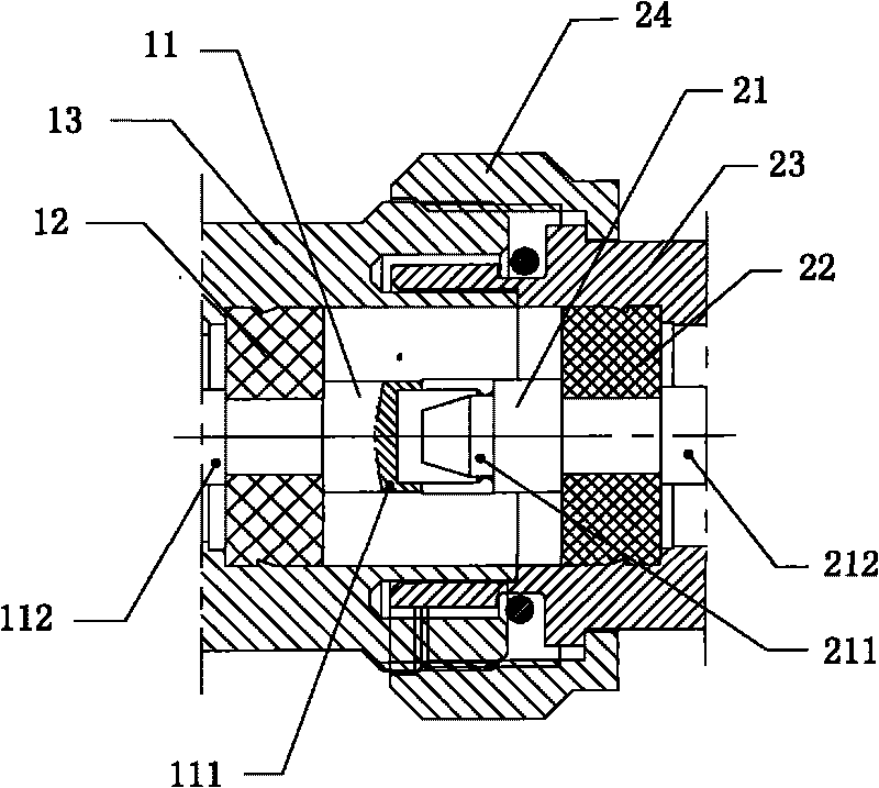
technical field [0001] The invention relates to cable connector technology, in particular to a coaxial cable connector female joint. Background technique [0002] Coaxial cables are widely used in various signal transmissions, especially video signal transmissions. Different cables need to be effectively connected in order to effectively transmit signals and avoid signal attenuation. For this reason, various coaxial cable connection devices have been used in the prior art. [0003] Such as figure 1 A coaxial cable connector of the prior art shown is a schematic cross-sectional view along the axial direction after the male connector and the female connector are plugged together, and this figure only shows the part related to the connection interface. The male joint consists of three layers of inner, middle and outer ring structures. The inner layer is a columnar central conductor 21, the middle layer surrounding the central conductor 21 is an insulator 22, and the outer lay...

Claims


Application Information

Patent Timeline
Patent Type & Authority Applications(China)
IPC IPC(8): H01R24/02H01R13/10H01R9/05H01R24/38
Inventor 宋志刚
Owner ROSENBERGER ASIA PACIFIC ELECTRONIC CO LTD
Learn More