Tail clamping and locking mechanism of low-frequency electric connector

A technology of electrical connectors and locking mechanisms, which is applied to parts, connections, circuits, etc. Diameter difference, anti-pull and other problems, to achieve good clamping effect, ensure electromagnetic compatibility, and high friction

Active Publication Date: 2010-05-05
CHINA NORTH IND GRP HANGLIAN TECH CO LTD
View PDF1 Cites 13 Cited by
  • Summary
  • Abstract
  • Description
  • Claims
  • Application Information

AI Technical Summary

Problems solved by technology

[0004] In order to solve the problem that the electric connector in the prior art clamps the cable through the shrapnel type clamp, the cable clamping surface is small, the friction force between the shrapnel type wire clamp and the cable is small, and the clamping force is small, which cannot meet the requirements of large diameter difference, pull resistance, Cable clamping with high torsion resistance requirements, and the production of the clamp is difficult, the production cost is high, the shrapnel type clamp is easy to deform after clamping, the maintainability is poor, the clamp is easy to scratch the outer layer of the cable, the shielding net, and the service life is short. The object of the present invention is to provide a compact structure, easy processing, low production cost, convenient installation and disassembly, large clamping surface between the clamping valve and the cable, large friction force, large clamping force, and the clamping valve is not easy to deform. Long service life, which can avoid damage to the outer layer of the cable and the clamping and locking mechanism at the end of the electrical connector of the shielding network

Method used


Image

  • Tail clamping and locking mechanism of low-frequency electric connector
  • Tail clamping and locking mechanism of low-frequency electric connector
  • Tail clamping and locking mechanism of low-frequency electric connector

Examples


Embodiment Construction

[0020] The present invention will be further described below in conjunction with drawings and embodiments.

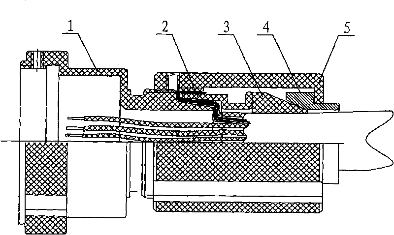
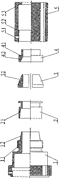
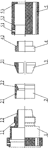
[0021] figure 1 , 2 In the first embodiment shown, a clamping and locking mechanism at the tail of a low-frequency electrical connector mainly includes a wire sheath 1 , a shielding sheath 2 , two clamping flaps 3 , a pressure ring 4 and a cable cover 5 . An outer conical surface 12 is provided on the tapered outer wall of the tail of the grommet 1, and the outer conical surface 12 is provided with an external thread 11. One end of the shielding sleeve 2 is provided with an inner conical hole 21 matching the outer conical surface 12, and the inner conical hole of the shielding sleeve 21 cooperates with the outer conical surface 12 of the wire sheath to press the cable shielding net, and the other end of the shielding sheath 2 abuts against one end face of the two clamping flaps 3, and the outer surface of the other end of the two clamping flaps 3 is a conical surface ...


PUM


Abstract

The invention relates to a tail clamping and locking mechanism of a low-frequency electric connector, comprising a protective line sleeve and a cable cover, wherein the protective line sleeve is connected with a plug or a socket of the electric connector; the cable cover is matched with the protective line sleeve and locks a cable; a contact line of the cable is welded with a pin of the plug or the socket connected with the protective line sleeve; two or more line clamping lamellas with excircle surfaces as conical surfaces are arranged between the protective line sleeve and the cable cover, and the excircle conical surfaces of the two or more line clamping lamellas face to the protective line sleeve or the cable cover and are in a symmetrical or uniformly distributing cable clamping state. The invention has the advantages of large line clamping area, high friction force between the line clamping lamellas and the cable, drag resistance and high twisting resistance; in addition, the line clamping lamellas can meet the requirement for clamping cables with large diameter differences according to the diameter design of the cables without deformation when used for a long time, is difficult to damage cable surface layers and shielding layers and has the advantages of convenient assembly and disassembly, repeated use, low cost and long service life.

Description

technical field [0001] The invention relates to a clamping and locking mechanism at the tail of an electric connector, in particular to a locking mechanism for clamping and shielding cables at the tail of a low-frequency electrical connector. Background technique [0002] The attachment of the cable at the tail of the traditional low-frequency electrical connector is a splint type. Two arc-shaped splints are connected to the cable cover. The two ends of the two splints are respectively provided with locking screws and gaskets. By screwing the locking screws Make the arc of the two clamping plates face the cable to clamp, and the shielding layer of the cable is wound on the locking screw to achieve the purpose of grounding. The structure adopts two arc-shaped clamping plates to clamp the cable. The contact surface between the curved surface of the clamping plate and the cable is relatively small, and the clamping is unstable. The local force on the cable locking part is too l...

Claims


Application Information

Patent Timeline
Patent Type & Authority Applications(China)
IPC IPC(8): H01R13/585
Inventor 叶学俊潘荣封燕郑新红
Owner CHINA NORTH IND GRP HANGLIAN TECH CO LTD
Why Eureka
Try Eureka