
Automatic capsule dropping coffee machine

A technology for coffee machines and capsules is applied in the field of automatic capsule-dropping coffee machines, which can solve the problems of only being installed on one side of the body, increasing the volume of the whole machine, and restricting the shape design, and achieves low manufacturing cost, small volume, and convenient production. control effect

Active Publication Date: 2010-05-12
GUANGDONG XINBAO ELECTRICAL APPLIANCES HLDG CO LTD
View PDF1 Cites 16 Cited by
  • Summary
  • Abstract
  • Description
  • Claims
  • Application Information

AI Technical Summary

Problems solved by technology

This structure realizes the rectilinear motion and automatic flipping of the brewing chamber through the principle of track control and linkage mechanism, and finally achieves the purpose of automatic bag drop. However, due to the flipping action of the brewing chamber, when the water outlet component and the water inlet component are opened, the distance between the two is separated. Larger, at least enough to turn over the brewing chamber and drop the capsules, and the volume of the whole machine will also increase accordingly; in addition, since the driving mechanism for driving the linear movement of the water outlet component is composed of two connecting rods, the rotating handle can only be installed on the body On one side, there are relatively large restrictions on the shape design, which needs to be further improved and perfected

Method used


Image

  • Automatic capsule dropping coffee machine
  • Automatic capsule dropping coffee machine
  • Automatic capsule dropping coffee machine

Examples


Embodiment Construction

[0031] The present invention will be further described below in conjunction with the accompanying drawings and embodiments.

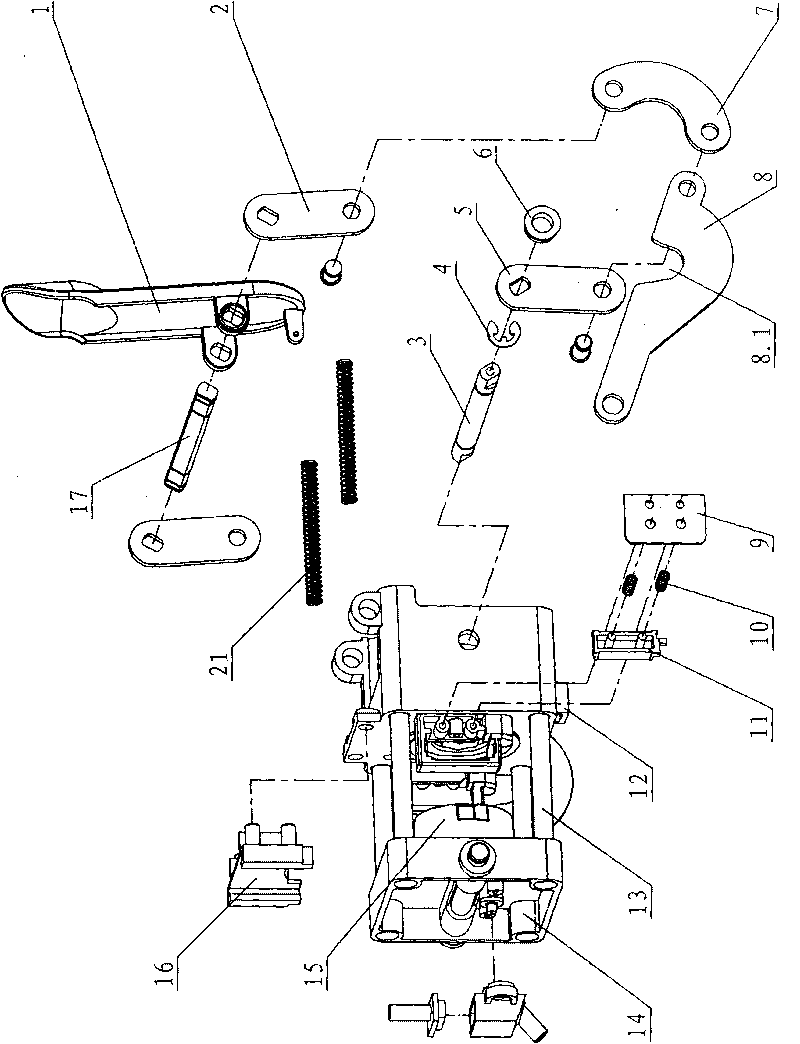
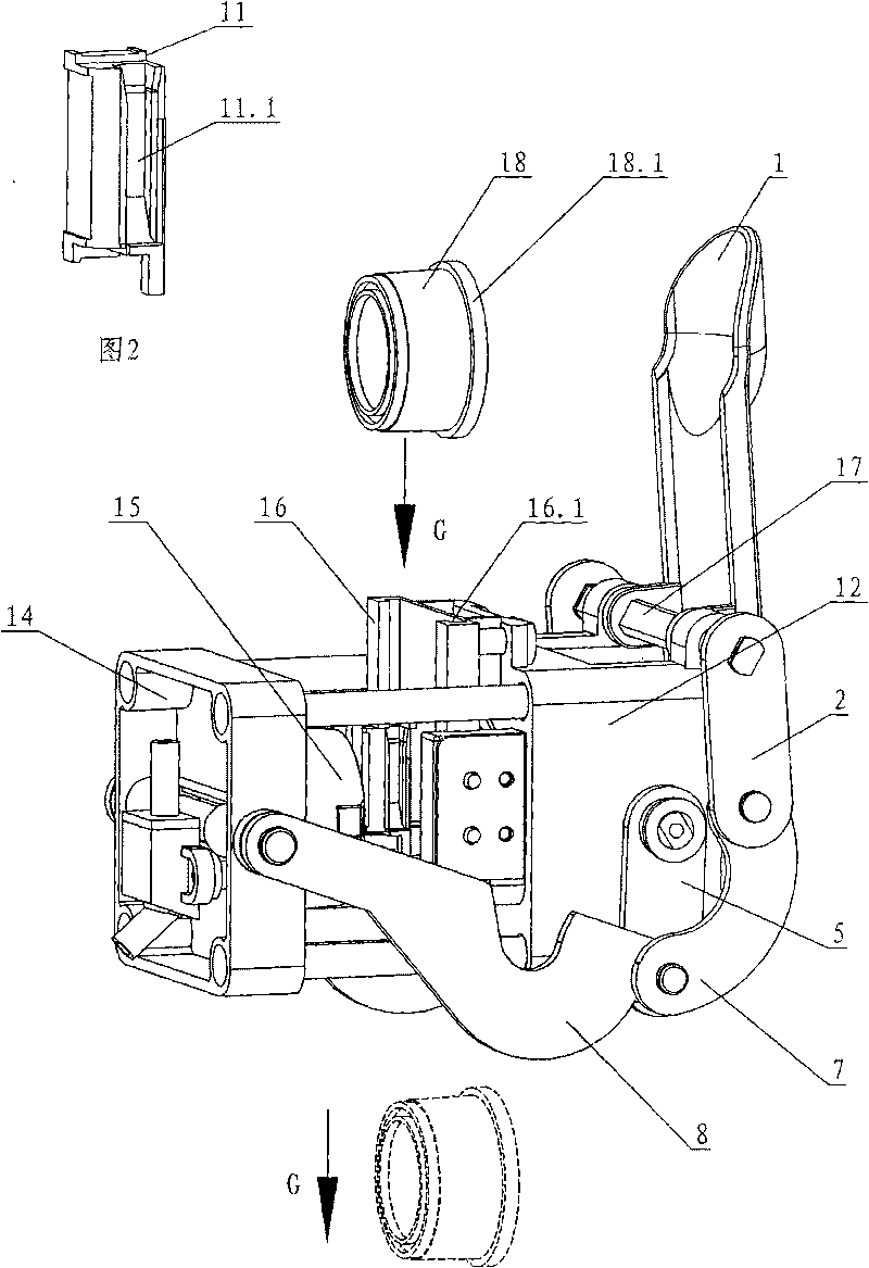
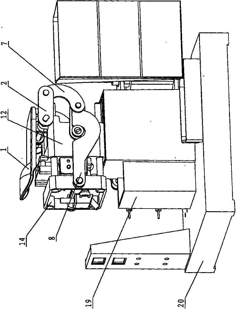
[0032] see Figure 1-Figure 8 , the automatic capsule coffee machine includes a water outlet assembly 14 and an inlet water assembly 12 that move along a straight line through a driving mechanism. The hot water channel for brewing coffee capsules and the one-way valve 12.2 are arranged at the end, see Figure 7 The surface of the coffee capsule is ring-shaped with a flange 18.1, the brewing chamber is fixed at the inner end of the water outlet assembly, and the opening of the coffee capsule is placed towards the hot water channel and the one-way valve; the left and right sides of the inner end of the water inlet assembly are provided with left and right sliding The movable clamping block 11 is provided with a card slot 11.1 corresponding to the flange of the coffee capsule. The water entry body assembly 12 is arranged on the machine base 20 , and a ca...


PUM


Abstract

The invention relates to an automatic capsule dropping coffee machine, which comprises a water outlet assembly and a water inlet assembly which carry out open and close movement mutually along a straight line through a driving mechanism. The water outlet assembly is provided with a brewing cavity for containing a coffee capsule; an inner end of the water inlet assembly is provided with a hot water channel and a one-way valve for brewing the coffee capsule; the surface of the coffee capsule is provided with a flange annularly; the brewing cavity of the coffee capsule is fixedly arranged at an inner end of the water outlet assembly; an opening containing the coffee capsule faces the hot water channel and the one-way value; both left and right sides of the inner end of the water inlet assembly are provided with movable fixture blocks which slide leftwards and rightwards; and the movable fixture blocks are provided with clamping grooves corresponding to the coffee capsule. When the water outlet assembly is separated from the water inlet assembly, the automatic capsule dropping coffee machine enables the coffee capsule to be vertical and the flange of the coffee capsule to be placed aiming at the clamping grooves of the movable fixture blocks; when the flange is in place, the water outlet assembly is closed; the brewing cavity pushes the movable fixture blocks off outwards gradually, and simultaneously the coffee capsule is sleeved in and is pushed to the hot water channel and the one-way value; and after brewing is completed, the water outlet assembly is opened, and the coffee capsule automatically drops off due to the action of gravity.

Description

technical field [0001] The invention relates to a capsule coffee machine, in particular to an automatic capsule coffee machine. Background technique [0002] Our company's Chinese patent document number CN101491415A disclosed a coffee capsule machine on July 29, 2009. It includes a brewer set in the machine body, which is characterized in that the brewer includes a water inlet assembly, a water outlet assembly, a drive mechanism for driving the water outlet assembly to perform linear motion, a brewing chamber for loading coffee capsules, and a connecting rod. There is a guide rail groove on the component, the follower of the driving mechanism is connected to the water outlet component, one end of the brewing chamber is connected to the water outlet component through a connecting fulcrum, the other end of the connecting rod is connected to the brewing chamber, and a positioning piece is installed on the connecting rod , the positioning piece is placed on the guide rail groov...

Claims


Application Information

Patent Timeline
Patent Type & Authority Applications(China)
IPC IPC(8): A47J31/40A47J31/10A47J31/44
CPCA47J31/3633A47J31/3638
Inventor 郭建刚刘育曾永春陈光华
Owner GUANGDONG XINBAO ELECTRICAL APPLIANCES HLDG CO LTD
Learn More