Clamp for processing double-head piston ball pit

A double-headed piston and ball pit technology, applied in the direction of manufacturing tools, workpiece clamping devices, etc., can solve the problems of poor positioning effect, easy damage to the embryo body, loose embryo body, etc. The effect of firm and accurate radial positioning and firm and accurate radial positioning

Active Publication Date: 2010-05-12
ZHEJIANG YIFENG MACHINERY
View PDF0 Cites 10 Cited by
  • Summary
  • Abstract
  • Description
  • Claims
  • Application Information

AI Technical Summary

Problems solved by technology

[0002] At present, the fixture used for the processing of the double-headed piston ball pit still adopts the traditional fixture. This kind of traditional fixture mainly includes a screw and a positioning block. The positioning block and the screw are connected by threads, and the positioning block can move back and forth through the rotation of the screw. , so as to complete the locking and positioning of the workpiece. Since the embryo body used for processing is mostly cylindrical, on this type of traditional fixture, its radial and axial positioning can only be completed by axial clamping. Positioning The effect is poor, and the embryo body is prone to slight loosening during processing. Since the ball pit of the double-headed piston needs to be processed repeatedly, the processing accuracy is high, and the slight looseness of the embryo body may affect the product quality; and because the screw itself It does not have a locking function. When the workpiece is under too much force, it will cause the screw to rotate, and the clamping effect will become poor, which will cause the embryo body to loosen, and it is easy to damage the embryo body during processing. Processing brings inconvenience

Method used


Image

  • Clamp for processing double-head piston ball pit
  • Clamp for processing double-head piston ball pit
  • Clamp for processing double-head piston ball pit

Examples


Embodiment 1

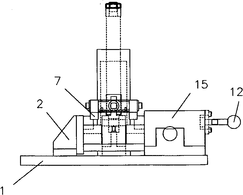
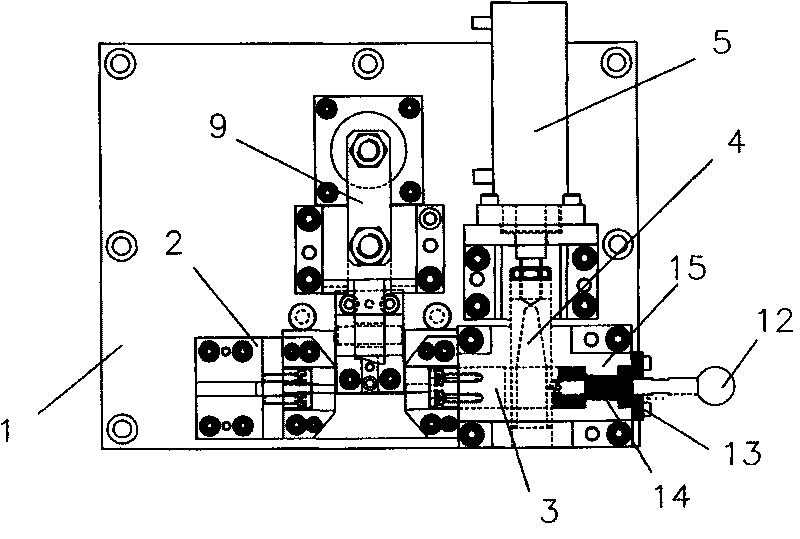
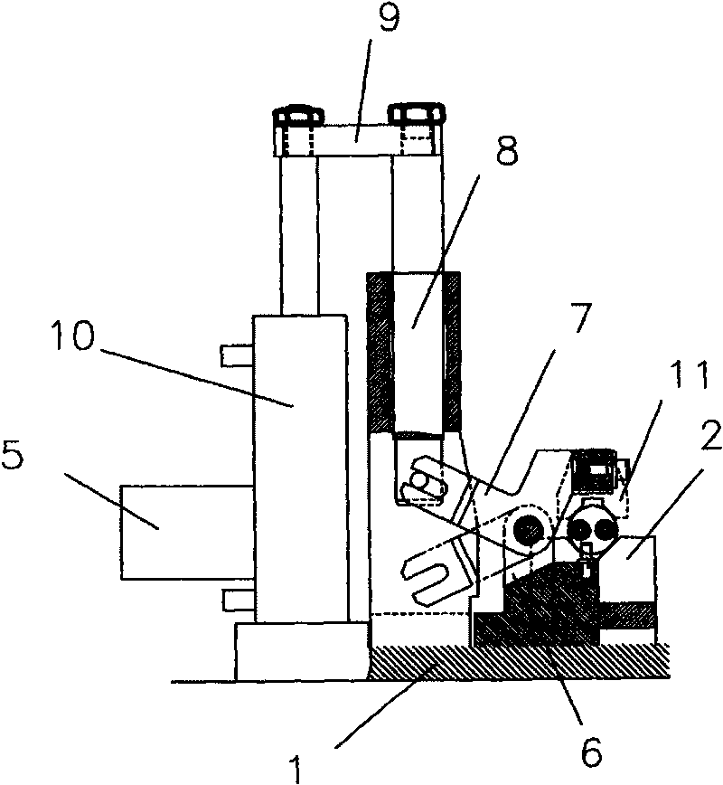
[0015] Such as figure 1 As shown, the fixture used for the processing of the double-headed piston ball pit described in this embodiment mainly includes a base plate 1 on which a positioning block 2 and a positioning block 2 are provided in the top tightening rod seat 15 to cooperate with the positioning block 2. The jacking rod 3 is provided with a telescopic pinning rod 4 on the side of the jacking rod 3, and the pinning rod 4 is connected with the first hydraulic cylinder 5 in transmission, and the bottom plate 1 is also provided with a pressing arm 7, and the pressing arm 7 A pressing arm 7 is arranged on the top, and the pressing arm 7 is installed on the pressing arm seat 6 through a hinge structure, and one end thereof is located above the positioning block 2 and is clamped with the positioning block 2 . The pinning rod 4 can play a good locking effect on the jacking rod 3. When the jacking rod 3 is positioned to press the workpiece, the pinning rod 4 can be operated to ...


PUM


Abstract

The invention discloses a clamp for processing a double-head piston ball pit, which mainly comprises a bottom plate. The bottom plate is provided with a positioning block and a puller rod seat, and the inside of the puller rod seat is provided with a puller rod which is positioned with the positioning block in a matching mode; the side of the puller rod is provided with a telescopic locking rod, and the locking rod is in transmission connection with a first hydraulic cylinder; the bottom plate is provided with a pressing arm seat, and the pressing arm seat is provided with a pressing arm; and the pressing arm is arranged on the pressing arm seat through a hinge structure, and one end of the pressing arm is positioned above the positioning block and clamped with the positioning block in the matching mode. The clamp can fix the puller rod through the locking rod and avoid the rollback phenomenon of the puller rod, so that work pieces are positioned more firmly in an axial direction; the pressing arm and the positioning block are matched, so the work pieces can be well pressed and fixed in a radial direction to prevent loosening, and the work pieces are positioned more firmly in the axial direction; the damage ratio of the work pieces is greatly reduced during the processing, and processing quality is also better.

Description

technical field [0001] The invention relates to a fixture positioning device, in particular to a fixture used for processing double-headed piston ball pits. Background technique [0002] At present, the fixture used for the processing of the double-headed piston ball pit still adopts the traditional fixture. This kind of traditional fixture mainly includes a screw and a positioning block. The positioning block and the screw are connected by threads, and the positioning block can move back and forth through the rotation of the screw. , so as to complete the locking and positioning of the workpiece. Since the embryo body used for processing is mostly cylindrical, on this type of traditional fixture, its radial and axial positioning can only be completed by axial clamping. Positioning The effect is poor, and the embryo body is prone to slight loosening during processing. Since the ball pit of the double-headed piston needs to be processed repeatedly, the processing accuracy is ...

Claims


Application Information

Patent Timeline
Patent Type & Authority Applications(China)
IPC IPC(8): B25B11/00
Inventor 陆富荣董建林张友明杨敏
Owner ZHEJIANG YIFENG MACHINERY
Why Eureka
Try Eureka