Continuous annealing furnace

A technology of annealing furnace and furnace body, which is applied in the directions of furnace, charge, furnace components, etc., can solve problems such as operation error, flue gas can not be discharged in time, and unreasonable structure design of air cooling and flue gas exhaust system.

Active Publication Date: 2019-12-20
杭州春风机械工程股份有限公司
View PDF9 Cites 2 Cited by
  • Summary
  • Abstract
  • Description
  • Claims
  • Application Information

AI Technical Summary

Problems solved by technology

[0005] 1. There is no relevant pipe detection device at each station in the furnace equipment, mainly relying on manual operation. For example, workers observe whether there is a pipe at the sand blowing station. If there is no pipe for sand blowing, the The well-aligned pipes at the middle station are transferred to the sand blowing station, and then the pipes at the in charge station are assigned to the centering station, and the work is cycled sequentially. This will undoubtedly greatly increase the labor of the workers. Low efficiency, and largely rely on manual operation, it is easy to cause operational errors, thus affecting the normal operation of the pipe;
[0006] 2. The cast iron pipes are transported in the annealing furnace through the chain claw conveyor chain. During the process of feeding the cast pipes to the chain claw conveyor chain in an orderly manner by the equipment in front of the furnace, for cast pipes with different diameters, each adjacent The number of claws between two cast tubes is different, for example, for small diameter pipe, every other chain claw is fed into the pipe, and for large diameter pipe, it may be required every two, three or four Each chain claw enters the pipe once. At present, the decision whether to enter the pipe every few chain claws or rely on manual operation is made. The worker stands at the pipe blocking mechanism and decides every few chain claws according to the diameter of the pipe by visual inspection. Operate the pipe blocking and discharging mechanism to enter the pipe once, which increases the labor load of workers and is inefficient;
[0007] 3. The conveyor chain in the furnace and the conveyor chain behind the furnace are driven by their own drive mechanisms, and the connection between the two is not good;
[0008] 4. Due to its unreasonable structural design, the air cooling and smoke exhaust system has the disadvantages that the air cooling effect is not good and the smoke cannot be discharged in time

Method used


Image

  • Continuous annealing furnace
  • Continuous annealing furnace
  • Continuous annealing furnace

Examples


Embodiment Construction

[0120] The present invention will be further described in detail below in conjunction with the accompanying drawings and examples. The following examples are explanations of the present invention and the present invention is not limited to the following examples.

[0121] Example.

[0122] see Figure 1 to Figure 43 .

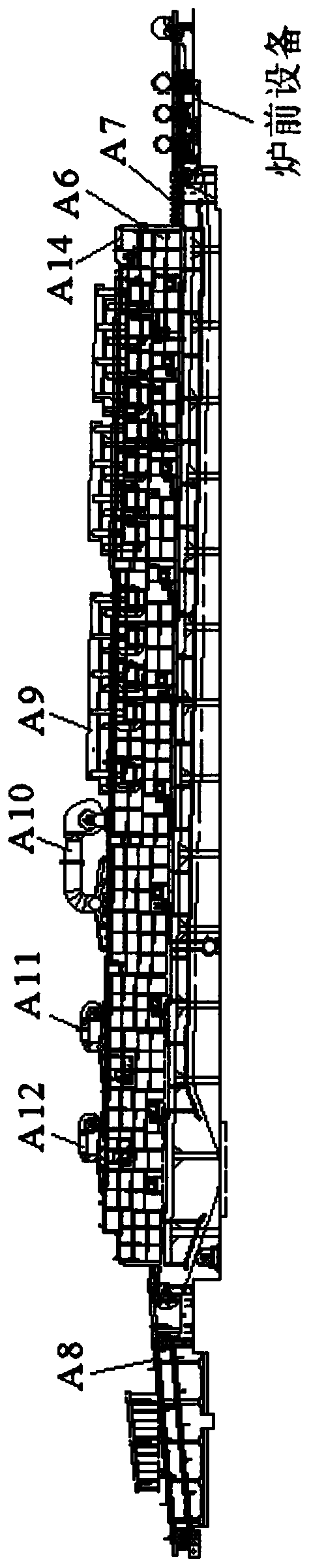
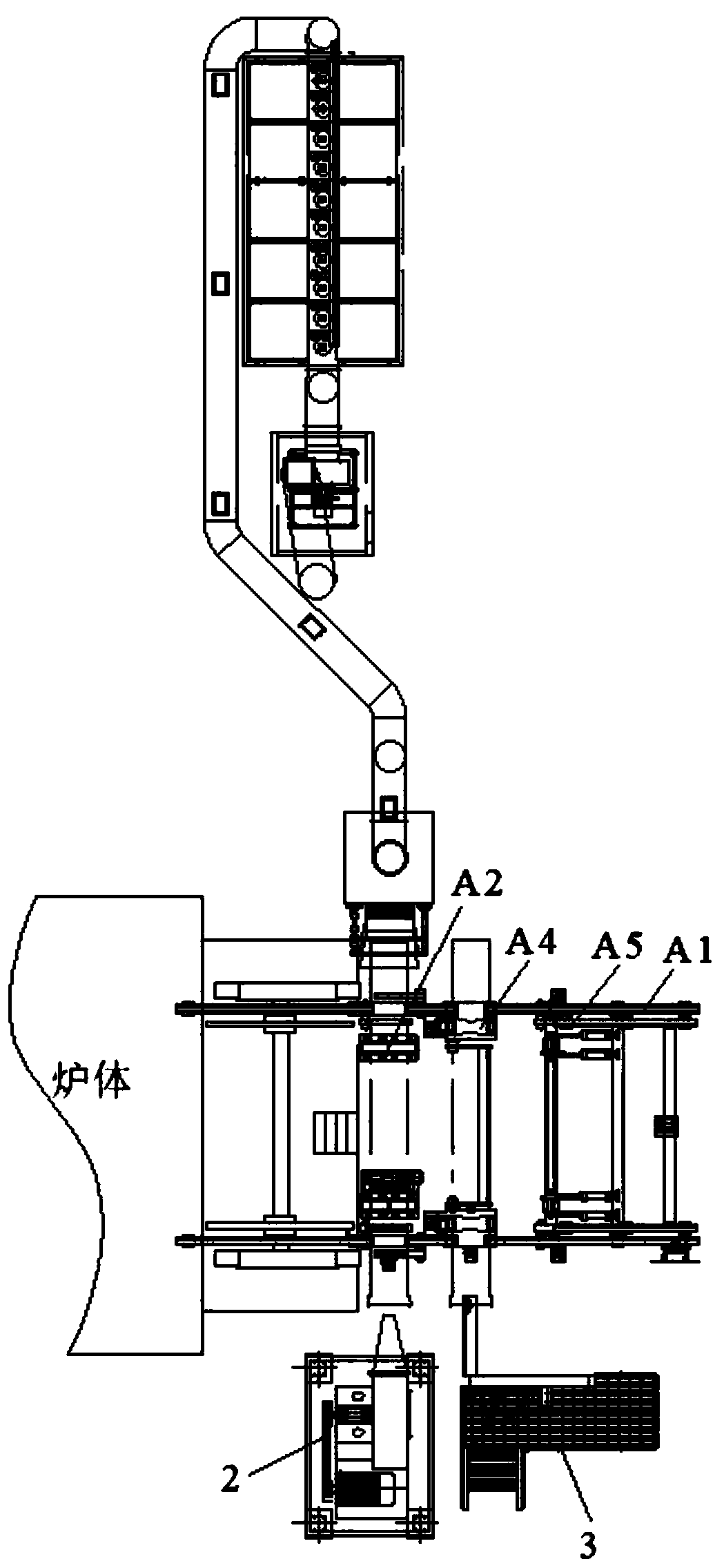
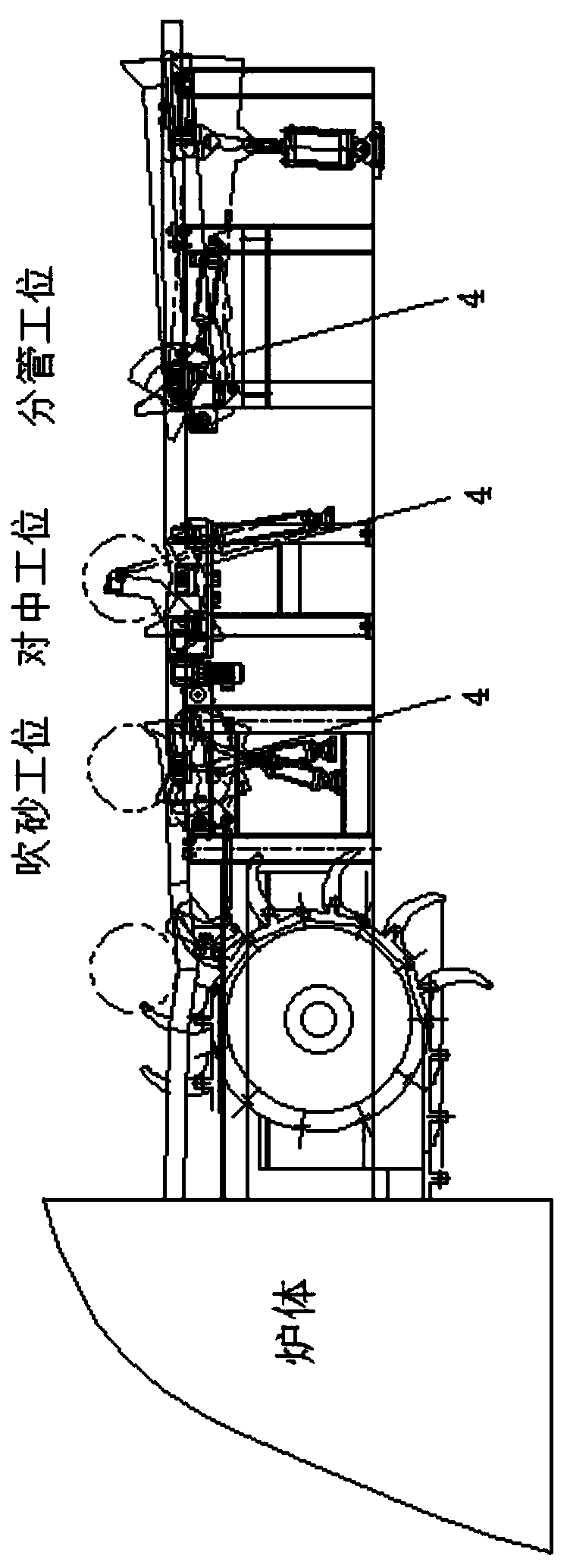
[0123] refer to figure 1 , This embodiment discloses a continuous annealing furnace, including a furnace body A6, a conveyor chain A7 in the furnace, a conveyor chain A8 behind the furnace and equipment in front of the furnace. The conveyor chain A7 in the furnace is installed in the furnace body A6, its input end protrudes from the entrance of the furnace body A6 and is connected with the equipment in front of the furnace, and its output end protrudes from the exit of the furnace body A6 and connects with the rear conveyor chain A8 connection, the furnace body A6 is sequentially installed with a combustion system A9, a fast cooling section air cooling and s...


PUM

PropertyMeasurementUnit
thicknessaaaaaaaaaa

Abstract

The invention relates to a continuous annealing furnace. An in-furnace conveying chain is arranged in a furnace body; an input end of the in-furnace conveying chain extends out from an inlet of the furnace body to be connected with pre-furnace equipment; an output end of the in-furnace conveying chain extends out from an outlet of the furnace body to be connected with a post-furnace conveying chain; a combustion system, a quick cooling section air cooling and smoke discharging system, a front slow cooling section air cooling system and a rear slow cooling section air cooling system are sequentially arranged on the furnace body from the inlet to the outlet; the pre-furnace equipment comprises a non-return device, a platform pipe presence detecting device, a pipe diameter measuring device and a sand blasting device, a pipe dividing mechanism, a centering mechanism, a supporting rotating mechanism and a pipe blocking and discharging mechanism; the pipe dividing mechanism, the centering mechanism, the supporting rotating mechanism and the pipe blocking and discharging mechanism are sequentially arranged in the pipe conveying direction; the quick cooling section air cooling and smoke discharging system is used for supplying cold air into the furnace body from the top and discharging smoke from the bottom of the furnace body; and the in-furnace conveying chain and the post-furnace conveying chain are driven by one driving mechanism. The continuous annealing furnace is reasonable in overall structural design and complete in system; and the pre-furnace equipment is high in automation degree and stable in pipe transportation, and special personnel do not need to watch pipes in real time.

Description

technical field [0001] The invention relates to the field of heat treatment equipment, in particular to a continuous annealing furnace. Background technique [0002] Ductile iron pipe refers to the pipe made by high-speed centrifugal casting of centrifugal ductile iron machine after casting molten iron above No. 18 with adding nodulizer, referred to as ball pipe, ductile iron pipe and ductile cast pipe, etc. The mechanical properties of cast iron pipes usually require heat treatment, and the continuous annealing furnace is a common equipment for heat treatment of cast iron pipes. [0003] Continuous annealing furnaces generally include furnace front equipment, furnace body, furnace conveyor chain, furnace conveyor chain, combustion system, air cooling and smoke exhaust system. The furnace front equipment is installed in front of the furnace entrance, and is used to feed the cast iron pipes into the furnace in an orderly manner. The furnace front equipment usually includes a...

Claims


Application Information

Patent Timeline
Patent Type & Authority Applications(China)
IPC IPC(8): C21D1/26C21D9/08F27D17/00G01B11/10G01V8/10
CPCC21D1/26C21D9/08F27D17/001G01B11/10G01V8/10F27M2003/01
Inventor 吴灵
Owner 杭州春风机械工程股份有限公司
Why Eureka
Try Eureka