Directional rzeppa universal joint

A universal joint and ball cage technology, applied in elastic couplings, mechanical equipment, couplings, etc., can solve the problems of motion trajectory interference, inconsistent force directions at contact points, and complex universal joint structures.

Inactive Publication Date: 2010-05-12
丛滨江 +1
View PDF0 Cites 8 Cited by
  • Summary
  • Abstract
  • Description
  • Claims
  • Application Information

AI Technical Summary

Problems solved by technology

The structure of the constant velocity spherical cage universal joint is complicated. Although the performance is higher than that of other universal joints, there are still problems of motion trajectory interference and inconsistent force direction of the contact point.

Method used


Image

  • Directional rzeppa universal joint
  • Directional rzeppa universal joint
  • Directional rzeppa universal joint

Examples


Embodiment Construction

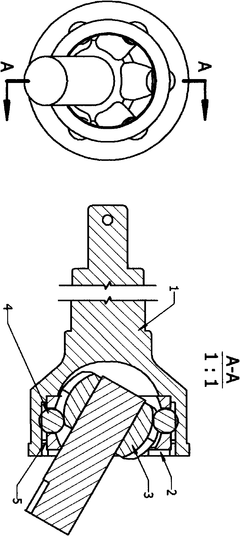
[0009] The first part: Orientation device, refer to the diagram to explain the structure;

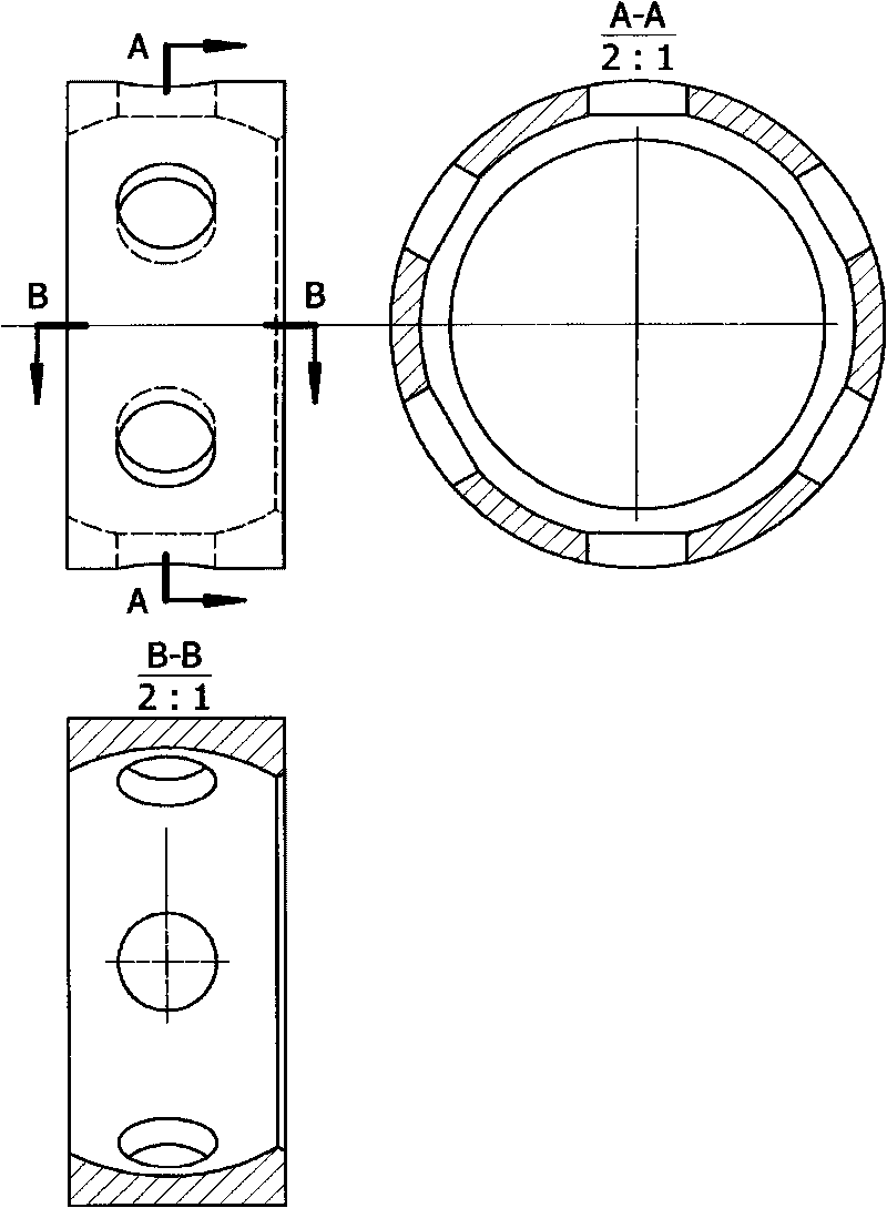
[0010] figure 1 Middle 1; Ball cage shell, 2; Cage, 3; Star wheel, 4; Steel ball, 5; Shaft card. The housing and the cage adopt a sliding fit. It can be seen from the figure that the cage is eccentric. The function of eccentricity is to allow the star wheel to fit into the cage and reserve a larger hole. Compared with the arc of the star wheel cage (see figure 2 ) is divided into two sections, one of which is transferred to the shell. The axial direction of the inner circle of the housing is provided with the same number of straight channels according to the number of steel balls to prevent slipping. When the cage and the star wheel are loaded into the spherical shell, the large end of the cage aperture faces inward, and the cage is positioned with a shaft card.

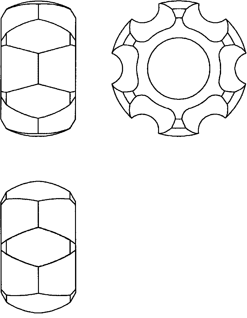
[0011] The second part; modification of star wheel, see appendix image 3 ;

[0012] The difficulty of X modification...


PUM


Abstract

The invention relates to a directional rzeppa universal joint with the operational principle of changing circumferential motion into plane intermittent motion. A horizontal intersecting plane of two axes is used as an acting surface, and the directional rzeppa universal joint gradually loses effectiveness when leaving the acting surface, being similar to installing a switch in a circumferential track, opening the switch for outputting power when each steel ball runs to two points at 90 degrees and 270 degrees (with 0 degree as a peak), and gradually closing the switch without exerting action after the steel balls leave the two points so as to eliminate interference. The directional rzeppa universal joint completely eliminates the operation mode of traditional rzeppa universal joints and achieves approximately unchanged transmission, unchanged angular speed and unchanged movement radii of the two connected axes when angles are changed by utilizing space alternating tracks, so that the directional rzeppa universal joint can run at completely equal speed, the track interference is eliminated, the bearing capacity is improved through the change of a main structure, and the directional rzeppa universal joint has three integrated degrees of freedom on a node, with which the past universal joint can not compare. In sum, the directional rzeppa universal joint can effectively work under all environments needing universal joints.

Description

technical field [0001] The invention relates to a universal mechanical component, a universal coupling for power transmission, which is mainly used to form a transmission device together with a transmission shaft, and is used between various power and loads that are not on one axis. Products are widely used in all mechanical fields. technical background [0002] The constant velocity spherical cage universal joint was invented in the United States and is mainly used in passenger cars. It has become a globally unified standardized component. The universal joint plus the connecting shaft becomes the transmission shaft assembly, which is used as the connection between two shafts with different axis directions. Among different universal joints, all passenger cars use constant velocity ball cage universal joints, because passenger cars The car requires stable transmission of power to reduce vibration, ensure that both ends of the shaft can rotate at a constant speed to avoid ste...

Claims


Application Information

Patent Timeline
Patent Type & Authority Applications(China)
IPC IPC(8): F16D3/223
Inventor 丛滨江
Owner 丛滨江
Why Eureka
Try Eureka