Infrared detector with adjustable detection range

An infrared detector and detection range technology, applied in the field of detectors and infrared detectors, can solve the problems of pet-proof performance defects, low acceptance, correct selection of installation locations, etc., to achieve reliable pet-proof performance, reduced operating burden, and acceptable degree of effect

Inactive Publication Date: 2010-05-12
JIANGSU XUANBO ELECTRONICS TECH
View PDF0 Cites 4 Cited by
  • Summary
  • Abstract
  • Description
  • Claims
  • Application Information

AI Technical Summary

Problems solved by technology

However, due to the weak circuit design and structural design capabilities of domestic security companies, insufficient research and development experience, and inaccurate product analysis and positioning, the existing passive infrared detectors have some inherent defects and have not been able to do so. Solve it fundamentally:
[0003] 1. Defects in anti-pet performance: most of the existing passive infrared detectors do not have the function of anti-pet. requirements, and the reliability is not high
If the pet is large or the distance between the pet and the probe is relatively close, the probe will still be triggered, and the reliability of its anti-pet function is very poor, and it is basically of no practical value
Preventing pets from triggering alarms is also a chronic problem that the existing traditional passive infrared detectors have not really solved;
[0004] 2. It does not have the function of preventing the user from triggering the alarm: the horizontal detection range of the existing passive infrared detector is basically a fan-shaped area of ​​about 90 degrees, and the detection range cannot be effectively partitioned and controlled
This makes the practicability of the product not strong, the user's operation burden is too large, and the user's acceptance of it is very low
This is also a serious obstacle limiting the popularity of its application;
[0005] 3. Requirements for the professional knowledge of installers and users: the existing infrared detectors are "too professional", and usually require installers to have certain security expertise and be able to carry out reasonable design and installation according to the actual situation on site and the performance of the detectors
But this is basically impossible. Ordinary users have almost no understanding of the basic performance, technical indicators and installation requirements of infrared detectors, so it is impossible to correctly select the installation location and adjust the infrared detector according to the actual situation;
[0006] 4. The vertical detection range has relatively large defects: At present, ordinary passive infrared detectors generally use flat infrared lenses, and their vertical detection range is actually a small fan-shaped range, generally around 26 degrees.
[0007] From the above analysis, it can be seen that the existing passive infrared detectors have "high professional knowledge requirements for installation and use, too complicated and difficult installation, can not effectively prevent pets from triggering alarms, and cannot effectively prevent users from triggering by themselves in the protection state." There are many major defects such as alarm and detection range with large dead angles. Due to the above major defects of ordinary infrared detectors, their practicability is not strong, and it is basically impossible for non-security professionals to install and use them correctly. This makes the scope of use of infrared detectors stay in engineering applications, and there is no way to promote and use them on a large scale in civil anti-theft. Promotion has been unsuccessful.

Method used


Image

  • Infrared detector with adjustable detection range
  • Infrared detector with adjustable detection range
  • Infrared detector with adjustable detection range

Examples


Embodiment Construction

[0031] In order to understand the technical content of the present invention more clearly, the following examples are given in detail.

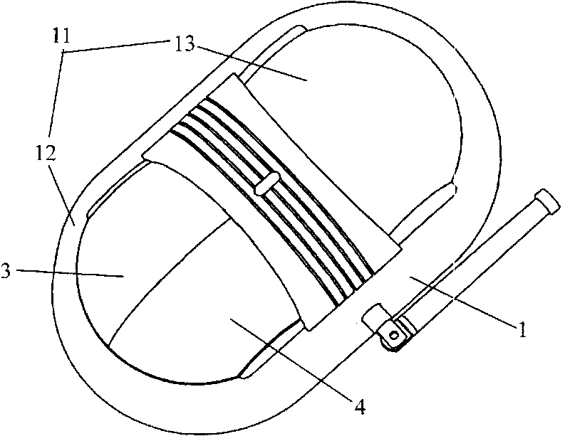
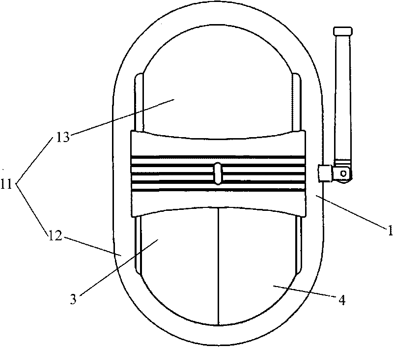
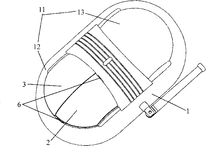
[0032] see Figure 1 ~ Figure 6bAs shown, the infrared detector with adjustable detection range of the present invention includes a casing 1 and an infrared lens 2, and the casing 1 includes a lower casing (not shown) and an upper casing fixed on the lower casing 11. The infrared lens 2 is installed on the upper casing 11, and the feature is that the infrared detector with adjustable detection range also includes a left protective flap 3 and a right protective flap 4, and the left protective flap 3 and the right protective cover 4 are detachably fixed on the upper housing 11 and cover the infrared lens 2.

[0033] Preferably, the infrared lens 2 is a spherical infrared lens. In a specific embodiment of the present invention, the spherical infrared lens is a quarter spherical infrared lens.

[0034] Preferably, the upper casing 11 includes ...


PUM


Abstract

The invention relates to an infrared detector with adjustable detection range, comprising a housing, an infrared lens, a left protection baffle plate and a right protection baffle plate, wherein the housing comprises a lower housing and an upper housing fixed on the lower housing; the infrared lens is installed on the upper housing; the left protection baffle plate and the right protection baffleplate are dismountablely fixed on the upper housing and cover the infrared lens; preferably, the infrared lens is a sphere infrared lens; the upper housing comprises a first end and a second end, andthe infrared lens is installed on the first end / the second end; and the left protection baffle plate and the right protection baffle plate are clamped with the upper housing. The infrared detector with adjustable detection range of the invention has artful design and convenient installation, effectively prevents pets and users from triggering to give alarm, can effectively protect doors, windowsand the like and is suitable for popularization and application on a large scale.

Description

technical field [0001] The invention relates to the technical field of detectors, in particular to the technical field of infrared detectors, in particular to an infrared detector with an adjustable detection range, which is applied to security and anti-theft alarm detection. Background technique [0002] The existing passive infrared detection technology has been widely used in the security alarm industry. Its basic working principle is to control the detection range through the infrared lens, and the infrared sensor inside the lens senses the mobile infrared signal in the corresponding range, thereby generating an alarm signal. Send it to the alarm host for processing. However, due to the weak circuit design and structural design capabilities of domestic security companies, insufficient research and development experience, and inaccurate product analysis and positioning, the existing passive infrared detectors have some inherent defects and have not been able to do so. So...

Claims


Application Information

Patent Timeline
Patent Type & Authority Applications(China)
IPC IPC(8): G01J5/04G01J5/08G08B13/19
Inventor 李洪坤李金良张必功
Owner JIANGSU XUANBO ELECTRONICS TECH
Why Eureka
Try Eureka