Moving cylinder efficient tubular oil pump

A high-efficiency pipe and oil well pump technology, which is applied in the direction of pumps, machines/engines, and liquid displacement machinery, etc., can solve the problems of increasing the leakage of oil inlet valves, large liquid resistance, and reduced pump efficiency, so as to increase the effective stroke , Reduce the downward bending, the effect of small oil inlet resistance

Inactive Publication Date: 2010-05-19
王志杰
View PDF0 Cites 0 Cited by
  • Summary
  • Abstract
  • Description
  • Claims
  • Application Information

AI Technical Summary

Problems solved by technology

The plunger of the above two pumps is inside the pump barrel and the oil outlet valve is fixed on the plunger. Due to the limitation of the diameter of the pump barrel, the oil outlet hole of the oil outlet valve cannot be enlarged, resulting in large liquid resistance.
In this way, when the plunger goes down, the liquid pressure in the pump cavity at the upper end of the oil inlet valve increases, which increases the leakage of the oil inlet valve, and the sucker rod bends and loses the effective stroke of the plunger, resulting in a decrease in pump efficiency.
In order to meet the production index requirements, it is necessary to increase the working parameters of the pumping unit, resulting in increased energy consumption and increased oil recovery costs

Method used


Image

  • Moving cylinder efficient tubular oil pump
  • Moving cylinder efficient tubular oil pump

Examples


Embodiment Construction

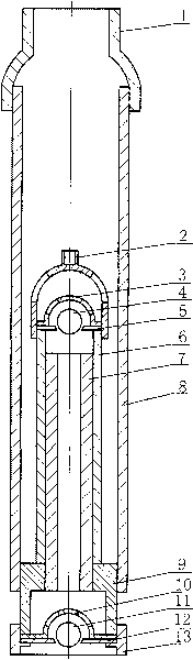
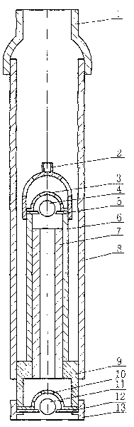
[0007] The present invention will be further described below in conjunction with accompanying drawing:

[0008] As shown in the figure, 1 is the upper joint of the pump body, 2 is the upper joint of the pump barrel, 3 is the oil outlet valve cover, 4 is the oil outlet valve ball, 5 is the oil outlet valve seat, 6 is the pump barrel, and 7 is the Plunger, 8 are outer pipes, 9 are plunger seats, 10 are oil inlet valve covers, 11 are oil inlet valve balls, 12 are oil inlet valve seats, and 13 are oil inlet valve joints.

[0009] The oil inlet valve is composed of an oil inlet valve seat 12, an oil inlet valve cover 10, and an oil inlet valve ball 11; the oil outlet valve is composed of an oil outlet valve seat 5, an oil outlet valve cover 3, and an oil outlet valve ball 4 composition.

[0010] When the pump barrel 6 goes up, the oil inlet valve is opened and the oil outlet valve is closed, and the liquid enters the pump chamber, and at the same time, the liquid discharged from t...


PUM


Abstract

The invention relates to a moving cylinder efficient tubular oil pump which belongs to the technical field of petroleum machinery. The moving cylinder efficient tubular oil pump is characterized in that one or a plurality of oil charging valves which are connected in series are arranged at the lower end of a plunger seat and are fixedly connected with an oil inlet valve seat joint through threads, one or a plurality of oil outlet valves in series connection are arranged at the upper end of a pump cylinder, an outer pipe is connected with the plunger seat and a plunger through the threads and then the lower end of the outer pipe forms a sealing cavity, and the plunger is fixed, and the pump cylinder is connected with an oil pumping rod through a cylinder pump upper joint and is also matched with the plunger in a sliding sealing way. The diameter of an oil inlet is larger than that of an inner hole of the plunger, therefore, the oil inlet resistance is little, and the oil filling degree of a pump cavity is high. Especially, the oil outlet valve is arranged on the pump cylinder, the oil outlet valve seat of the pump is not limited by the diameter of the pump cylinder, the diameter can be enlarged, the oil outlet resistance is little, the descending bending of the oil pumping rod is reduced, the effective stroke of the pump cylinder of the oil pump is increased, and the efficiency of the oil pump is improved.

Description

technical field [0001] The invention belongs to the technical field of petroleum machinery and relates to an improvement of an oil well pump used for oil recovery in an oil field. Background technique [0002] Rod well pumps widely used in oilfields at present, no matter the tube pump or the rod pump, the pump barrel is connected to the oil pipe, and the plunger moves back and forth with the sucker rod in the pump barrel to pump oil. The plunger of the above two pumps is in the pump barrel and the oil outlet valve is fixed on the plunger. Due to the limitation of the diameter of the pump barrel, the oil outlet hole of the oil outlet valve cannot be enlarged, resulting in large liquid outlet resistance. In this way, when the plunger goes down, the liquid pressure in the pump chamber at the upper end of the oil inlet valve increases, which increases the leakage of the oil inlet valve, and the effective stroke of the plunger is lost due to the bending of the sucker rod, resulti...

Claims


Application Information

Patent Timeline
Patent Type & Authority Applications(China)
IPC IPC(8): F04B47/02E21B43/00
Inventor 王志杰
Owner 王志杰
Why Eureka
Try Eureka