Supercharge Your Innovation With Domain-Expert AI Agents!

Suspension structure for serpentine tube panel

A technology of suspension structure and serpentine tube, which is applied in the direction of boiler support/positioning device, etc., can solve the problems that the expansion cannot be effectively released and the cost of header 1 is high, and achieve the effects of easy maintenance, simple structure and high mechanical properties

Active Publication Date: 2011-05-25
SHANGHAI BOILER WORKS
View PDF0 Cites 0 Cited by
  • Summary
  • Abstract
  • Description
  • Claims
  • Application Information

AI Technical Summary

Problems solved by technology

The cost of header 1 is relatively high, and the arrangement of header 1 needs to consider the flow of soda and water. The connection method between the tube panel and header 1 determines that the tube panel can swing horizontally, but the vertical expansion cannot be effectively released

Method used


Image

  • Suspension structure for serpentine tube panel
  • Suspension structure for serpentine tube panel
  • Suspension structure for serpentine tube panel

Examples


Embodiment

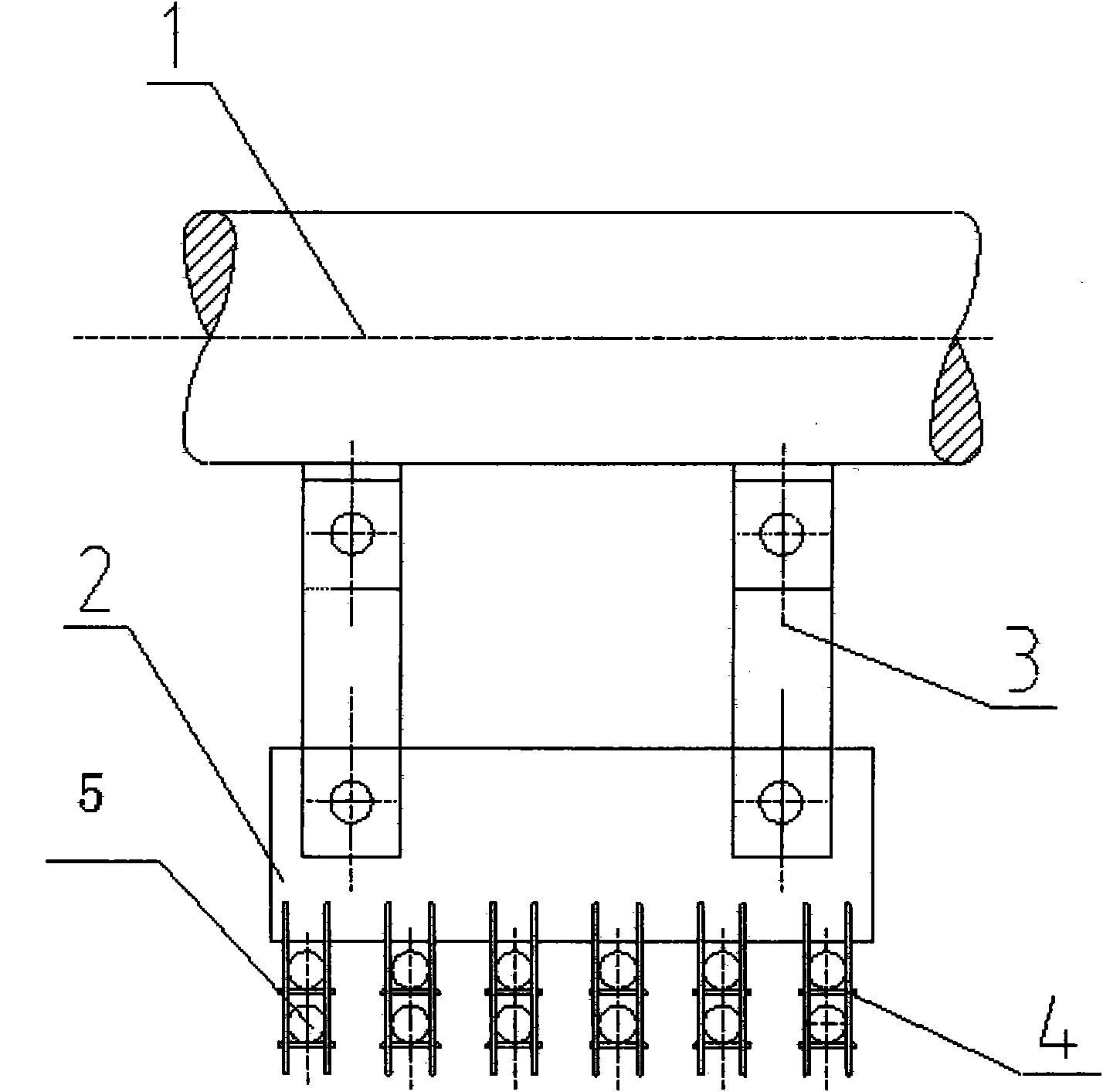
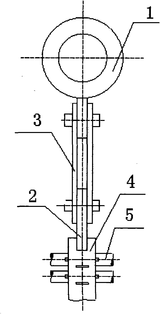
[0014] Such as image 3 and Figure 4 As shown, a suspension structure for a serpentine tube panel provided by the present invention includes a tube clamp 4, a serpentine tube panel 5 passes through the tube clamp 4, and a return-shaped steel plate 6 is provided on the top of the tube clamp 4, The back-shaped steel plate 6 runs through the steel beam 7, and its end is arranged outside the steel beam 7, and angle steel 8 is welded on both sides of the end of the back-shaped steel plate 6, and the angle steel 8 is placed on the steel beam 7, and on the steel beam 7 and the back The corresponding place of the through hole on the shaped steel plate 6 has a hole 9. A reinforcing rib is provided on the angle steel 8 .

[0015] In the present invention, the load-bearing element is changed from the header to the steel beam 7. First, it can be used in the rear smoke shaft where the intermediate header is inconvenient to arrange, and the layout scheme is more flexible; secondly, the s...


PUM


Abstract

The invention relates to a suspension structure for a serpentine tube panel, which is characterized by comprising U-shaped plates, wherein two sides of each serpentine tube forming the snakelike tube panel are respectively and symmetrically provided with a U-shaped plate; a steel plate is respectively and horizontally arranged on the two sides of the snakelike tube panel; the steel plates are erected on the U-shaped plates; and a girder is provided with holes corresponding to through holes on the steel plates. The suspension structure has the advantages of simple structure, high strength and convenient installation.

Description

technical field [0001] The invention relates to a suspension structure for reducing the swing of the tube panel and transferring the weight of the horizontal tube. Background technique [0002] Conventional suspension structures for serpentine tube panels such as figure 1 and figure 2 As shown, the serpentine tube screen 5 passes through the pipe clamp 4, the pipe clamp 4 is welded on the steel plate 2, and the two ends of the connecting plate 3 are respectively connected with the steel plate 2 and the steel plate pin welded on the intermediate header 1 through pin shafts. The cost of header 1 is relatively high, and the layout of header 1 needs to consider the flow of soda and water. The connection method between the tube panel and header 1 determines that the tube panel can swing horizontally, but the vertical expansion cannot be effectively released. Contents of the invention [0003] The purpose of the present invention is to provide a suspension structure with bett...

Claims


Application Information

Patent Timeline
Patent Type & Authority Patents(China)
IPC IPC(8): F22B37/24
Inventor 李立薛凌云赵井冈
Owner SHANGHAI BOILER WORKS
Features
  • R&D
  • Intellectual Property
  • Life Sciences
  • Materials
  • Tech Scout
  • Unparalleled Data Quality
  • Higher Quality Content
  • 60% Fewer Hallucinations
Learn More