Magnetic resonance diagnostic apparatus and magnetic resonance diagnostic method
A diagnostic device, magnetic resonance technology, applied in the direction of diagnosis, diagnostic recording/measurement, medical science, etc., can solve problems such as deterioration, larger motion artifacts, and higher costs
- Summary
- Abstract
- Description
- Claims
- Application Information
AI Technical Summary
Problems solved by technology
Method used
Image
Examples
no. 1 Embodiment approach
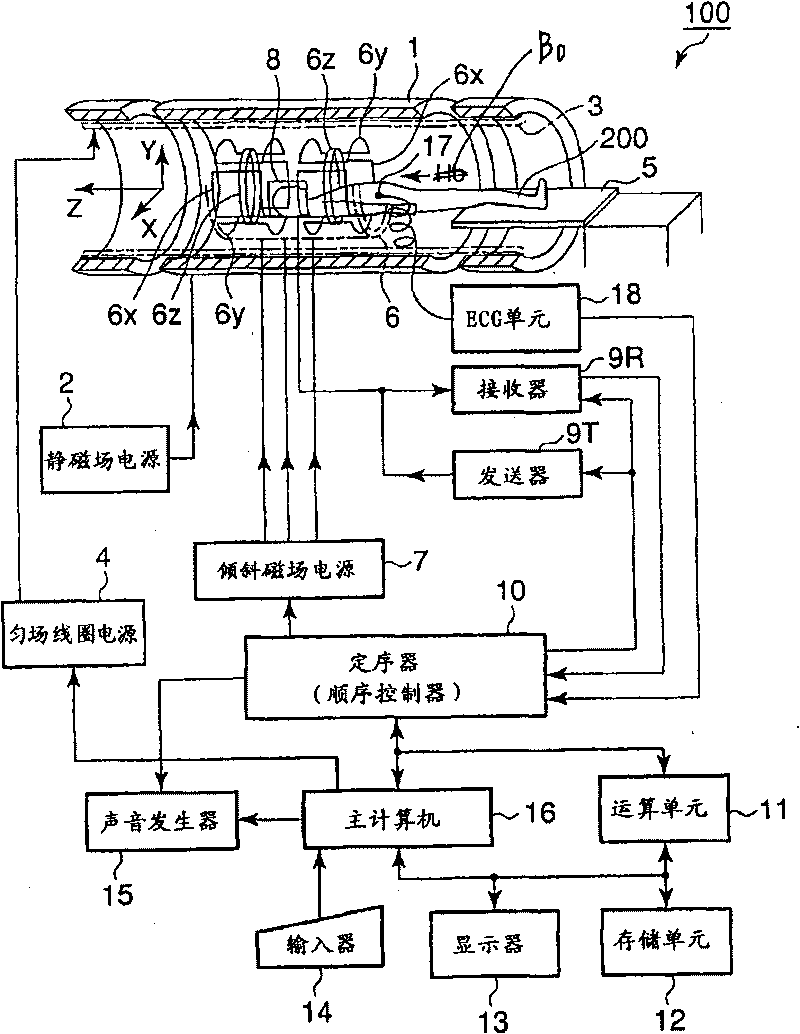
[0053] Hereinafter, the operation in the first embodiment of the magnetic resonance diagnostic apparatus 100 will be described.
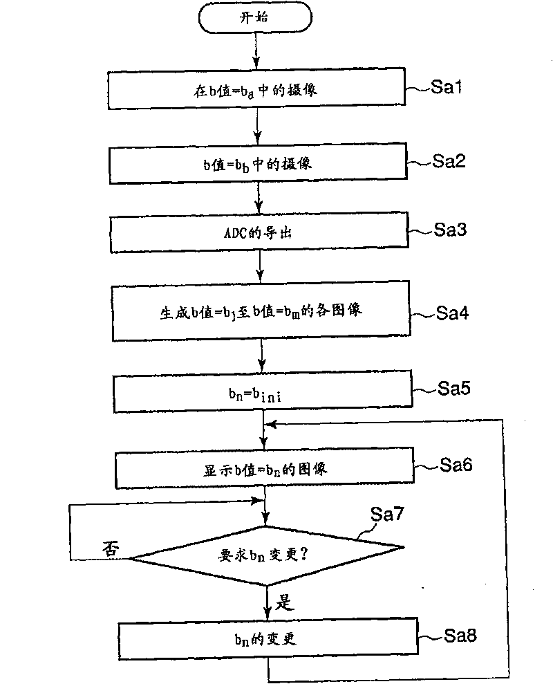
[0054] figure 2 It is a flowchart showing the processing procedure in the first embodiment of the host computer 16 .
[0055] In step Sa1, the host computer 16 sends an instruction to the sequencer 10 to set the b value to the preset value b for the preset region of interest. a camera. The sequencer 10 operates the gradient magnetic field power supply 7, the transmitter 9T, the receiver 9R, and the arithmetic unit 11 according to the instruction, so that the operation using the held value b a The b-value of the camera. Hereinafter, the image captured here will be referred to as a first original image.
[0056] Additionally, the value b a It can be any value, but it is better to take 0. in b a When =0, T2-enhanced imaging using the SE (spin echo: spin echo) method or the FSE (fast spin echo: fast spin echo) method can be used for the imaging ...
no. 2 Embodiment approach
[0077] The operation of the second embodiment of the magnetic resonance diagnostic apparatus 100 will be described below.
[0078] Figure 6 It is a flowchart showing the processing procedure of the second embodiment of the host computer 16 . In addition, in the same figure 2 The same symbols are assigned to the same processes, and detailed description thereof will be omitted.
[0079] In step Sb1 , the host computer 16 determines which part of the subject the part to be imaged (hereinafter, referred to as an imaging part) to be performed in the future is. The determination of the imaging site can be performed based on user designation input via the input unit 14, for example.
[0080] In step Sb2, the host computer 16 sends an instruction to the sequencer 10 to set the b value to the set value b related to the imaging site for the preset region of interest. a camera. The sequencer 10 activates the gradient magnetic field power supply 7, the transmitter 9T, the receiver ...
no. 3 Embodiment approach
[0098] The operation of the third embodiment of the magnetic resonance diagnostic apparatus 100 will be described below.
[0099] Figure 8 It is a flowchart showing the processing procedure of the third embodiment of the host computer 16 . In addition, in the same figure 2 The same symbols are assigned to the same processes, and detailed description thereof will be omitted.
[0100] The host computer 16 first captures the first original image in step Sa1 in the same manner as in the first embodiment, and then proceeds to step Sc1.
[0101] In step Sc1, the host computer 16 determines the imaging site, and acquires the diffusion coefficient D related to the imaging site. Diffusion coefficients vary for anatomical tissues in the human body, and standard diffusion coefficients are known for normal tissues. Therefore, pre-set as Figure 9 The shown information tables are stored in the storage unit 12 in association with the anatomical tissues that may serve as imaging sites...
PUM
 Abstract
Description
Claims
Application Information
 - R&D
- Intellectual Property
- Life Sciences
- Materials
- Tech Scout
- Unparalleled Data Quality
- Higher Quality Content
- 60% Fewer Hallucinations
Browse by: Latest US Patents, China's latest patents, Technical Efficacy Thesaurus, Application Domain, Technology Topic, Popular Technical Reports.
© 2025 PatSnap. All rights reserved.Legal|Privacy policy|Modern Slavery Act Transparency Statement|Sitemap|About US| Contact US: help@patsnap.com


