
Catalyst unloading device

A catalyst and vacuum device technology, which is applied in the direction of transportation and packaging, conveying bulk materials, chemical instruments and methods, etc., can solve the problems of reducing the broken rate of catalysts, and achieve the effect of improving the efficiency of unloading agent and reducing the broken rate

Active Publication Date: 2010-05-26
JIANGSU TIANPENG PETROCHEMICAL TECH CO LTD
View PDF4 Cites 9 Cited by
  • Summary
  • Abstract
  • Description
  • Claims
  • Application Information

AI Technical Summary

Problems solved by technology

[0008] Aiming at the problems existing in the existing catalyst unloading method and the characteristics of the current hydrogenation devices getting higher and higher, the present invention designs a new type of catalyst unloading device, which can not only improve the catalyst unloading efficiency, but also significantly reduce the catalyst unloading efficiency. Broken rate

Method used


Image

  • Catalyst unloading device
  • Catalyst unloading device
  • Catalyst unloading device

Examples


Embodiment Construction

[0015] The present invention will be further described in detail below in conjunction with the drawings and specific embodiments.

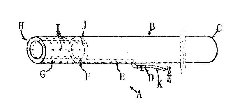
[0016] Such as figure 1 Shown is a schematic perspective view of the vacuum device of the present invention.

[0017] In the first aspect of the present invention, the vacuum device is composed of an extension tube with a determined aperture, and the proximal end of the tube is connected to the suction assembly to transport the catalyst along the inner diameter from the far end of the tube to the proximal end of the tube. The end is equipped with a spray assembly that introduces a large number of compressed gas nozzles into the inner cavity of the distal region of the tube. It is preferable that a large number of compressed gas nozzle holes are in the longitudinal cross-sectional direction of the tube, and it is beneficial that the compressed nozzle directly radially enters the inner cavity of the tube.

[0018] Generally speaking, the spray assembly co...


PUM


Abstract

The invention provides a catalyst unloading device and a method for removing solid catalyst or other solid material from a reactor. The remote end of the tube of a specially-made vacuum device is inserted into the solid catalyst, and a large quantity of fluid nozzles are connected with the cavity of the remote end area of the tube, so that the solid catalyst is loosened, and the loosened solid catalyst is sucked from the remote end to the near end of the tube along the tube. By adopting the device, the vacuum tube can be always positioned on the back of the bed layer of the catalyst, thereby improving the conveying efficiency. In addition, by directly inserting the tube into the reactor through a manhole, the overflow of the catalyst is avoided. In addition, an ideal air gap between the bed layer of the catalyst and a traditional vacuum tube conveyor which are closed to each other is required to be achieved, and the solid catalyst or other solid material can be removed because of the effect of a flow core. As gas is continuously and effectively conveyed to the remote end of the tube, the problem that material can not be conveyed when the distance inserted into the bed layer by a traditional vacuum tube exceeds a limit value can be avoided.

Description

Technical field [0001] The invention relates to a novel catalyst unloading device for petrochemical plants. Background technique [0002] The bed of the hydrocracking unit is very high, and the waste catalyst needs to be reused. Using the existing vacuum equipment to unload the agent, the catalyst has a high crushing rate, which cannot meet the requirements of the waste catalyst for reuse. [0003] The catalyst unloading method involved in CN1376765A is currently the most advanced catalyst unloading method in the catalyst service industry. Flame retardants are used to treat the catalyst surface to form a special film on the catalyst surface, and then vacuum unloading is performed. This method can provide a cleaner unloading environment, but it is not suitable for hydrocracking units with higher and higher beds. The vacuum suction method and device used lead to a higher rate of catalyst fragmentation. [0004] CN1724137A and CN2808283Y relate to a method and device for unloading a si...

Claims


Application Information

Patent Timeline
Patent Type & Authority Applications(China)
IPC IPC(8): B65G53/14B01J8/02
Inventor 姚晟赵静
Owner JIANGSU TIANPENG PETROCHEMICAL TECH CO LTD
Learn More