Scroll expander

A scroll expander and expansion mechanism technology, applied in the field of scroll expanders, can solve problems such as low suction efficiency, and achieve the effects of preventing the decline of suction efficiency, reliable lubrication, and high efficiency

Inactive Publication Date: 2010-05-26
PANASONIC CORP
View PDF8 Cites 1 Cited by
  • Summary
  • Abstract
  • Description
  • Claims
  • Application Information

AI Technical Summary

Problems solved by technology

[0006] However, in order to lubricate sliding parts other than the sliding parts of the fixed scroll and movable scroll, such as bearings or rotation control mechanisms, it is necessary to install other oil supply pumps, etc.
[0007] Moreover, when oil is supplied according to Bernoulli's theorem, since the refrigerant flowing into the expansion chamber from the working fluid introduction pipe pumps up the lubricating oil, when the flow rate of the inflowing refrigerant is large, a large amount of lubricating oil will be sucked in, so there is a suction effect. inefficiency

Method used


Image

  • Scroll expander
  • Scroll expander
  • Scroll expander

Examples


Embodiment 1

[0048] Embodiments of the present invention will be described below with reference to the drawings. The present invention is not limited to the description of the examples.

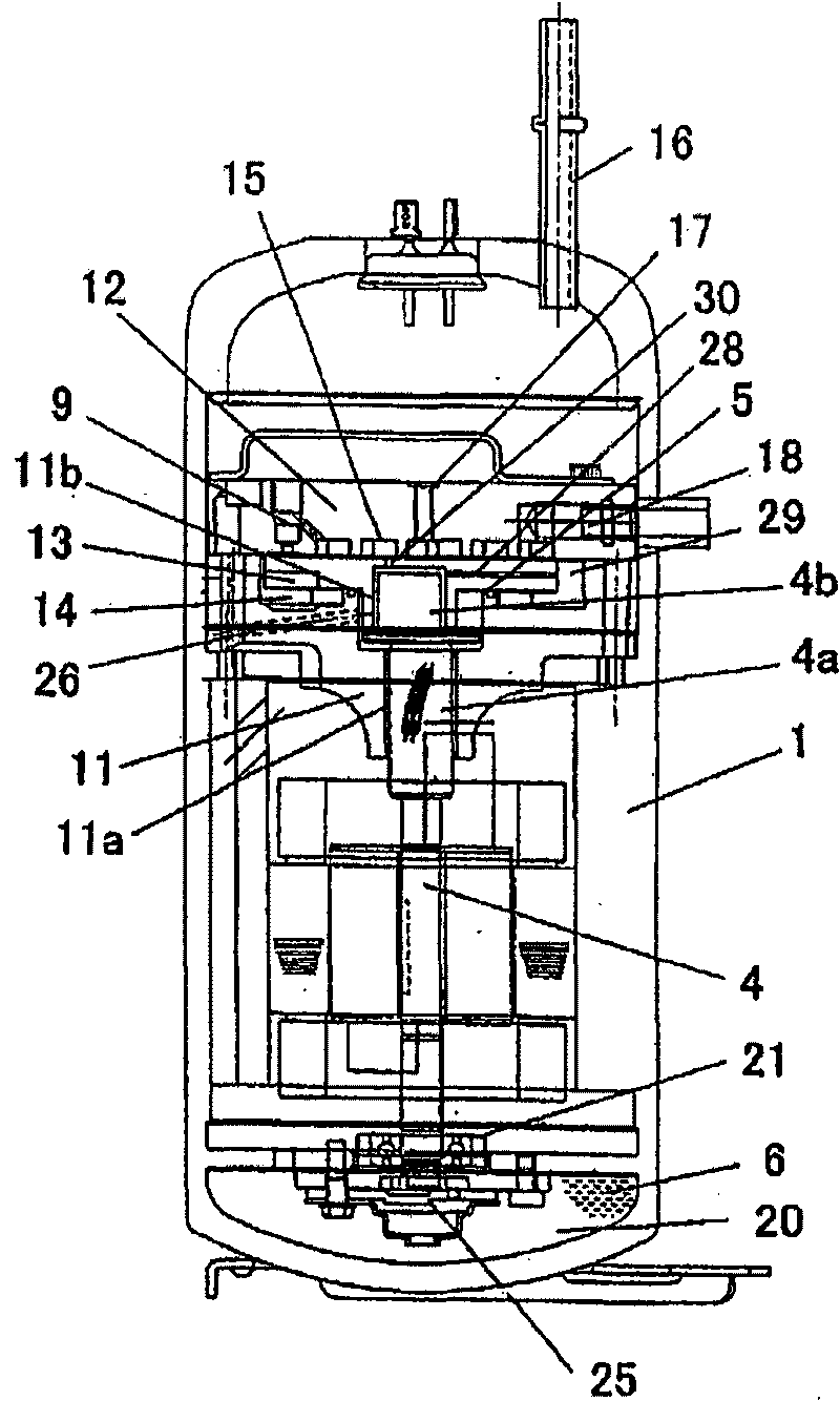
[0049] figure 1 is a sectional view showing the scroll expander in Embodiment 1 of the present invention.

[0050] In the scroll expander in this embodiment, the movable scroll 13 engaged with the fixed scroll 12 is clamped between the main bearing part 11 and the fixed scroll 12 fastened on the main bearing part 11 by bolts, and the main bearing The member 11 supports the main shaft portion 4a of the crankshaft 4 fixed in the sealed container 1 by welding, shrink fitting, or the like. Between the movable scroll 13 and the main bearing member 11 is provided a rotation control mechanism 14 such as an oldam ring which prevents the movable scroll 13 from rotating and guides it in a circular orbital motion.

[0051] In the above structure, the movable scroll 13 is moved in a circular orbit by eccentricall...

Embodiment 2

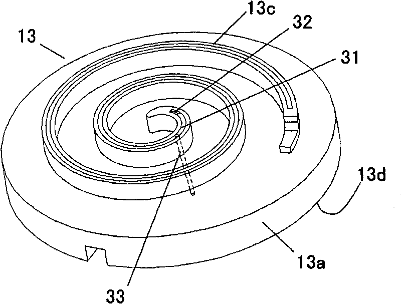
[0060] image 3 It is a perspective view showing the movable scroll of the scroll expander in Embodiment 2 of the present invention.

[0061] In the scroll expander of this embodiment, a sealing sheet storage groove 32 is formed on the front end of the scroll portion 13 c of the movable scroll 13 for storing the sealing sheet 31 . On the end plate 13a, a passage 33 communicating between the bottom surface of the sealing sheet storage tank 32 and the end plate back surface 13d is formed.

[0062] With this structure, the lubricating oil 6 can fill the gap between the seal plate storage tank 32 and the seal plate 31, thereby improving the sealing performance of the refrigerant leaking out of the scroll portion 13c, and providing a high-performance scroll expander.

[0063] In addition, since the lubricating oil 6 passes through the gap between the sealing plate storage tank 32 and the sealing plate 31, along with the expansion process, it lubricates the sliding parts of the fix...

Embodiment 3

[0066] Figure 4 ~ Figure 6 It is an explanatory diagram showing the sealing process of the refrigerant by the scroll expander in Embodiment 3 of the present invention. The process in which the refrigerant is enclosed by the two scroll portions is illustrated according to the rotation angle of the crankshaft. Here, the first passage 30a indicates a position provided on the end plate 13a of the movable scroll 13 (not shown).

[0067] Figure 4 The moment when the first expansion chamber 15a is formed is shown. That is to say: the contact portion 34 produced by the contact between the inner wall side of the scroll portion 13c of the movable scroll 13 and the outer wall side of the scroll portion 12c of the fixed scroll 12 forms the state of the first expansion chamber 15a (just closed). later state).

[0068] Figure 5 and Figure 6 A state in which the first expansion chamber 15a is sequentially expanded by the counterclockwise rotation of the movable scroll 13 (a state r...


PUM


Abstract

To improve both the reliability and performance of an scroll expander.Lubricating oil 6 held at a suction pressure is supplied into a counter-lap side end plate rear face 13d of a revolving scroll 13. Communicating passages 30a and 30b to communicate the end plate rear face 13d and the lap bottom 13b of the revolving scroll center portion are formed to the end plate 13a. Thereby, since the lubricating oil 6 is supplied into a suction part, and discharged lubricating and sealing a fixed scroll 12 and the revolving scroll 13 successively following the expansion process, so as to provide the relible scroll expander.

Description

[0001] This application is a divisional application of the invention patent application submitted by Matsushita Electric Industrial Co., Ltd. with the application number 200610099633.8 and the application date of April 28, 2006. technical field [0002] The present invention relates to a scroll expander in which an expansion chamber is formed between a fixed scroll and a movable scroll, and when the movable scroll rotates according to the rotation control of the rotation control mechanism, the volume of the expansion chamber is changed simultaneously. Move to carry out the suction, expansion and discharge of the working fluid. Background technique [0003] Conventionally, in this type of scroll expander, in order to lubricate the sliding surfaces of the fixed scroll and the movable scroll, the lubricating oil stored at the bottom of the seal box is pumped up by an oil supply pump and supplied. However, since complex cutting and the like must be required to manufacture the fu...

Claims


Application Information

Patent Timeline
Patent Type & Authority Applications(China)
IPC IPC(8): F01C1/02F04C18/02
Inventor 鶸田晃森本敬泽井清
Owner PANASONIC CORP
Why Eureka
Try Eureka