Evaporator

A technology of evaporator and liquid collection tank, which is applied in the direction of evaporator/condenser, indirect heat exchanger, heat exchanger type, etc. It can solve the problems of increased flow path resistance, performance degradation, and large ratio, and achieve refrigerant flow The effect of increasing the cross-sectional area of ​​the passage, preventing the rapid rise of the exhaust gas temperature, and preventing the increase of the flow passage resistance

Inactive Publication Date: 2010-05-26
KEIHIN THERMAL TECH CORP
View PDF1 Cites 15 Cited by
  • Summary
  • Abstract
  • Description
  • Claims
  • Application Information

AI Technical Summary

Problems solved by technology

As a result, the liquid-phase refrigerant flowing into the refrigerant passages of the heat exchange tubes of each heat exchange tube group remains in the gas-liquid mixed-phase refrigerant in the refrigerant inlet header and the refrigerant outlet header of the upper header tank. The amount becomes relatively small, and the effect of preventing the exhaust temperature from rising sharply when the compressor stops is not ideal.
[0006] In addition, the tip of the insertion portion of the heat exchange tube becomes horizontal, and the maximum distance in the vertical direction from the tip of the insertion portion of the heat exchange tube to the inner surface of the connecting wall of the convex portion of the refrigerant inlet header and the refrigerant outlet header As the size becomes larger, the flow resistance in the refrigerant inlet header and the refrigerant outlet header increases, which may degrade performance.
In particular, if the flow path resistance in the refrigerant outlet header increases, the ratio of the gas-phase refrigerant existing in the refrigerant outlet header will increase, so performance degradation may be significant.

Method used


Image

  • Evaporator
  • Evaporator
  • Evaporator

Examples


Embodiment Construction

[0055] Hereinafter, embodiments of the present invention will be described with reference to the drawings.

[0056] In addition, in the following description, the term "aluminum" includes aluminum alloys in addition to pure aluminum. In addition, in the following description figure 1 The left and right are called left and right.

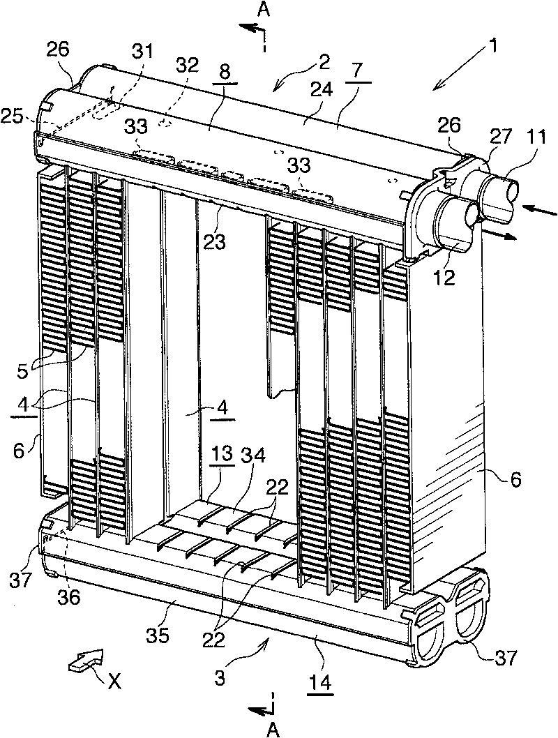
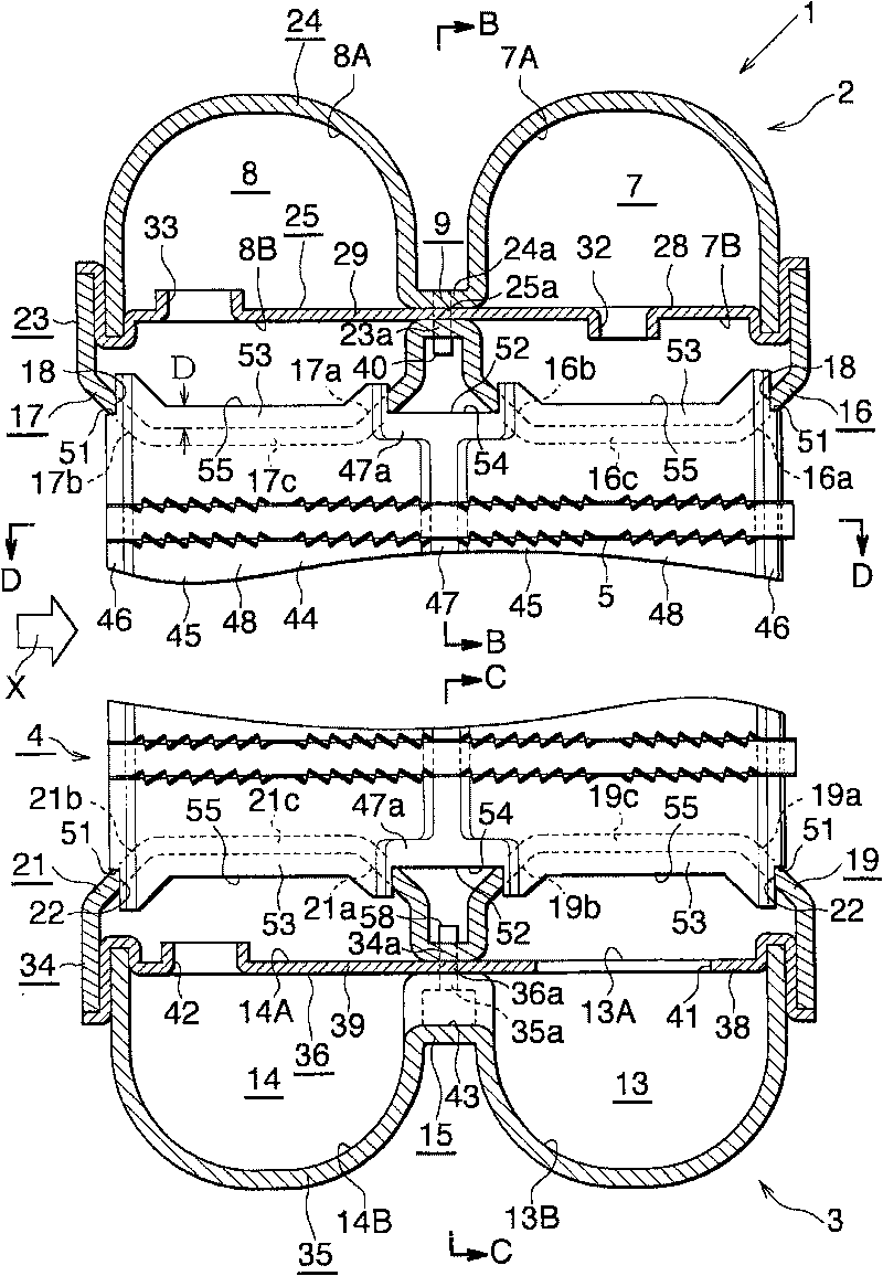
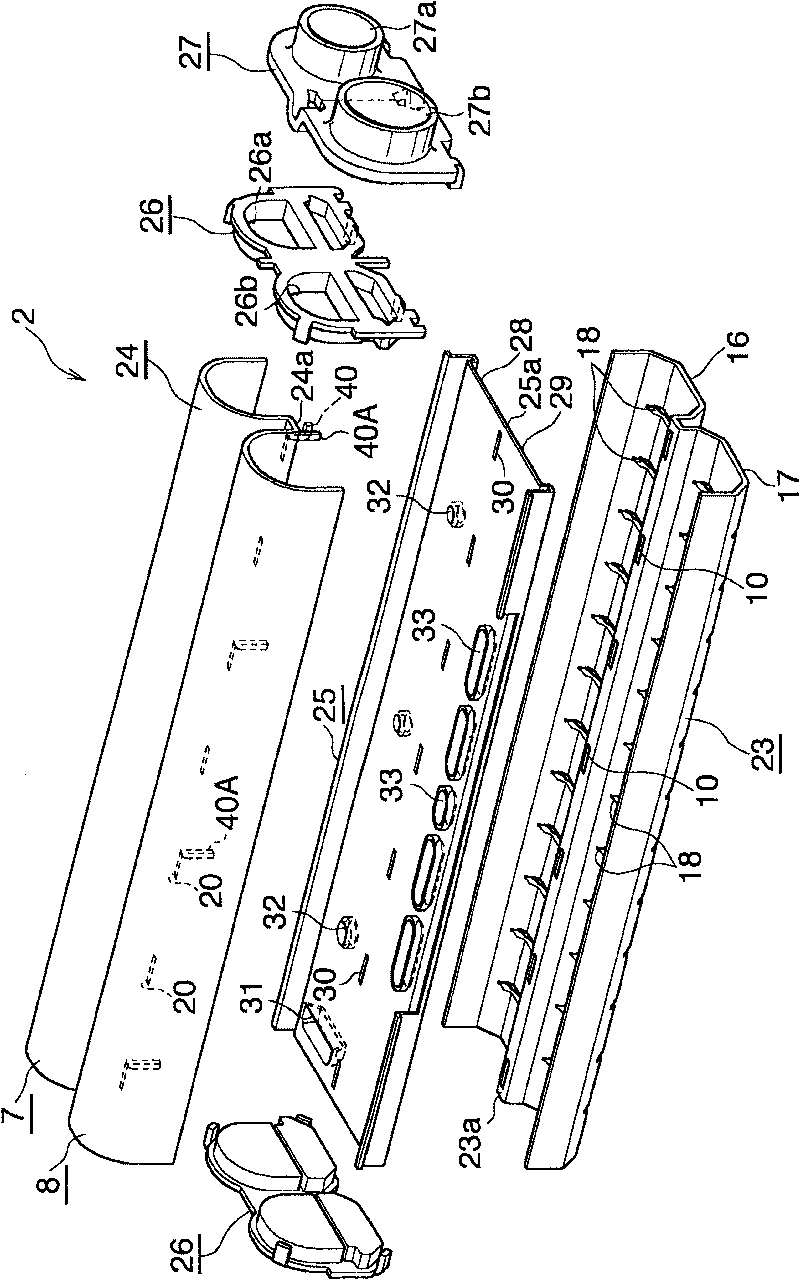
[0057] figure 1 Indicates the overall composition of the evaporator, Figure 2 to Figure 9 Shows the main components of the evaporator.

[0058] Such as figure 1 as well as figure 2 As shown, the evaporator 1 has: a first header tank 2 made of aluminum and a second header tank 3 made of aluminum that are arranged at intervals in the up-down direction and extend in the left-right direction; in the two headers 2 , 3, the width direction is oriented in the front and rear direction and in the left and right directions (the length direction of the header tanks 2, 3) are arranged at intervals in a plurality of aluminum flat heat exchange tubes 4; The ventilati...


PUM


Abstract

Each heat exchange tube of an evaporator is composed of two press-worked rectangular metal plates joined together in a stacked condition. The metal plates of the heat exchange tube are swelled outward whereby at least one refrigerant flow space extending in the vertical direction and having opened upper and lower ends is provided in the heat exchange tube. Insertion portions to be inserted into header sections of header tanks of the evaporator via tube insertion holes are provided on upper and lower end portions of each heat exchange tube at positions corresponding to the refrigerant flow space. A concave portion is formed in each of the insertion portions, excluding opposite ends thereof with respect to the front-rear direction, of the upper and lower end portions of each heat exchange tube, the concave portion being concaved inward with respect to a longitudinal direction of the heat exchange tube.

Description

Technical field [0001] The present invention relates to an evaporator suitable for use as a vehicle air conditioner installed in, for example, a refrigeration cycle of a motor vehicle. Background technique [0002] In this specification and claims, the downstream side of the air flowing through the ventilation gap between the adjacent heat exchange tubes ( figure 1 , figure 2 as well as Picture 10 The direction indicated by the arrow X) is called front, and the opposite side is called back, and figure 1 , figure 2 as well as Picture 10 Up and down is called up and down. [0003] In recent years, as an evaporator for vehicle air-conditioning capable of achieving smaller size, lighter weight, and higher performance, the applicant has earlier proposed the following evaporator (refer to Japanese Patent Application Laid-Open No. 2008-20098). A pair of header tanks arranged at intervals in the direction and a plurality of flat heat exchange tubes made of aluminum extruded profiles, t...

Claims


Application Information

Patent Timeline
Patent Type & Authority Applications(China)
IPC IPC(8): F25B39/02
CPCF28F1/128F28D1/05391F28F9/182F28F9/0278F25B39/022F28F9/0224F28D2021/0085
Inventor 高木基之东山直久峯北斗
Owner KEIHIN THERMAL TECH CORP
Why Eureka
Try Eureka