Dual fuel engine

A dual-fuel engine and liquid fuel technology, applied to combustion engines, internal combustion piston engines, engine components, etc., can solve problems such as increased equipment costs and failure to meet exhaust gas limit values

Inactive Publication Date: 2004-05-26
NIIGATA POWER SYST CO LTD
View PDF0 Cites 23 Cited by
  • Summary
  • Abstract
  • Description
  • Claims
  • Application Information

AI Technical Summary

Problems solved by technology

However, because the NO in the exhaust X The value is high and cannot meet the increasingly stringent exhaust gas limit value in the future. It is necessary to use a denitrification device for post-treatment, which will cause the problem of increased equipment costs.

Method used


Image

  • Dual fuel engine
  • Dual fuel engine
  • Dual fuel engine

Examples


Embodiment Construction

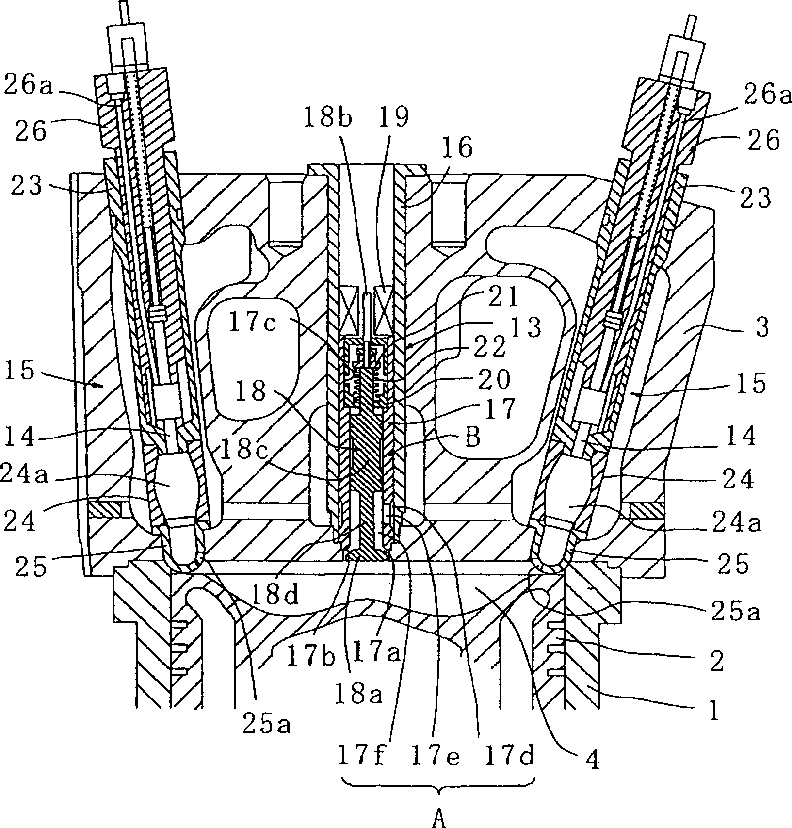
[0036] Embodiments of the present invention will be described below with reference to the drawings.

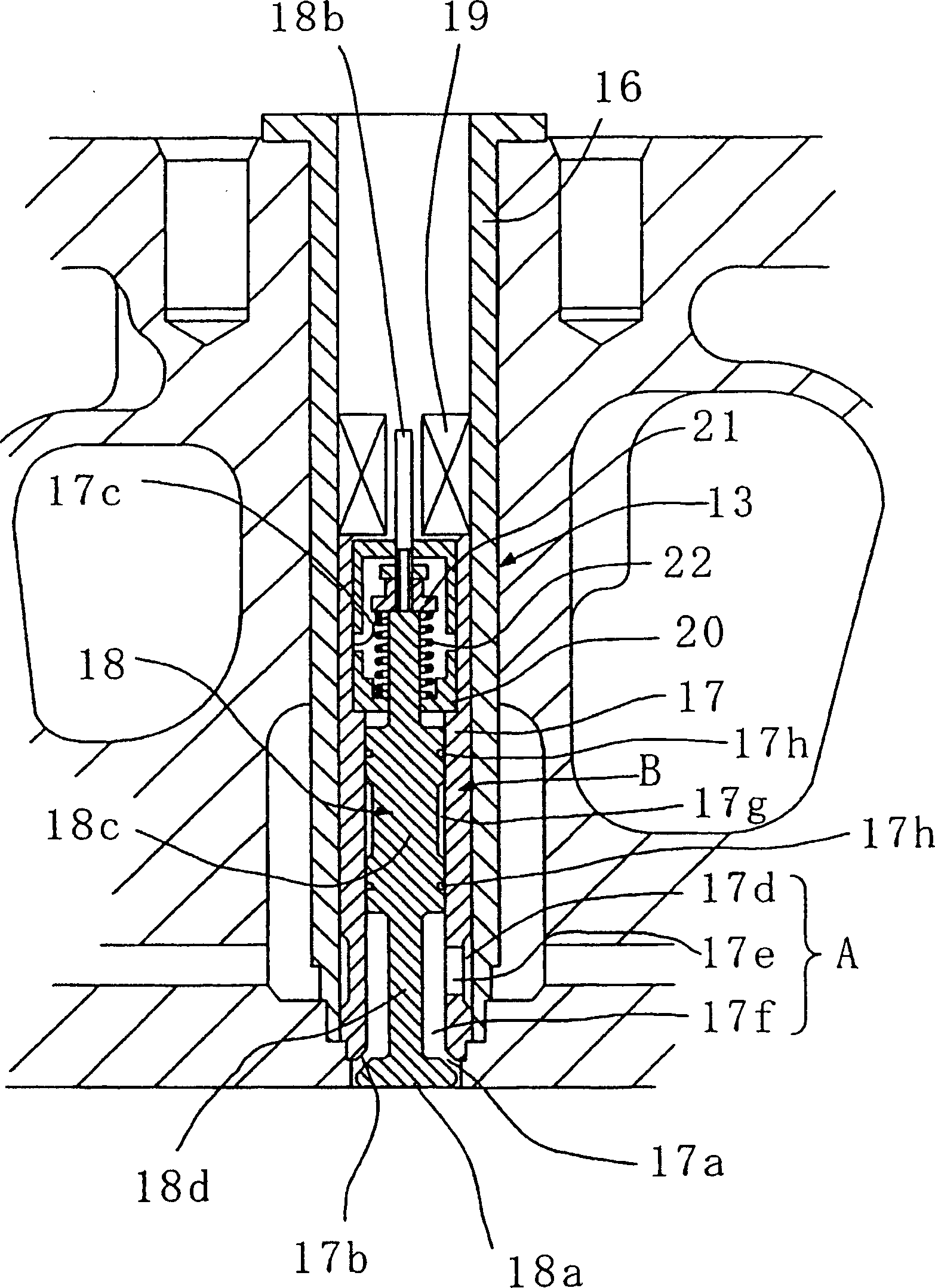
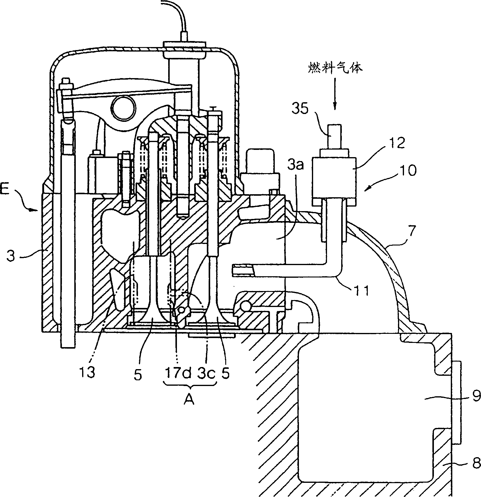
[0037] figure 1 and image 3 is a longitudinal sectional view of one side and the other side of a cylinder head portion of a dual-fuel engine E related to the present invention, figure 2 yes figure 1 A partial enlargement of the . exist Figure 1 ~ Figure 3 Among them, 1 is a cylinder liner of the dual-fuel engine E, and a piston 2 reciprocating with the rotation of the crankshaft is arranged in the cylinder liner 1. 3 is a cylinder head having an air intake port 3a and an exhaust port (not shown), 4 is the main combustion chamber surrounded by above-mentioned cylinder liner 1, piston 2 and cylinder head 3. On the intake port 3a of cylinder head 3 and the exhaust port (not shown), the intake valve 5 and the exhaust valve ( not shown).

[0038] The intake port 3 a is connected to an intake manifold 9 provided on the cylinder block 8 through an intake manifold 7 . A gas...


PUM


Abstract

A dual fuel engine, which is designed to allow choosing between gas operation and diesel operation, with low emission of NOx ensured even during diesel operation, and which is capable of adjusting the compression ratio during the gas operation according to the operating state, so as to provide a quick start and an operation with high combustion efficiency, throughout the load region, comprising a cylinder head that is provided with a compression ratio control valve, and a pre-combustion chamber unit having a pre-combustion chamber and an electromagnetic type fuel injection valve liquid fuel injection valve. The compression ratio control valve opens/closes a communication port connecting a main combustion chamber and an inlet port. In the gas operation, the valve opening period of the compression ratio control valve is adjusted according to the rotary state.

Description

technical field [0001] The present invention relates to a dual-fuel engine that supports either gaseous fuel or liquid fuel by selecting an operation mode. Background technique [0002] Currently, there are known dual-fuel engines capable of operating in two modes: a gas operation mode using gaseous fuel and a Diesel operation mode using liquid fuel, as an engine for driving a power generation device. As an example of this type of engine, there is an engine that can switch the operating mode, that is, when the gas is running, a small amount of pilot oil (accounting for about 5 to 15% of the total heat) is injected through the liquid fuel injection valve located at the center of the cylinder head. ) is used as an ignition source to burn gaseous fuel; and in the Diesel operation mode, 100% of the liquid fuel injected from the above-mentioned liquid fuel injection valve is burned to run. [0003] In this dual fuel engine, the compression ratio is lower than that of the Diesel ...

Claims


Application Information

Patent Timeline
Patent Type & Authority Applications(China)
IPC IPC(8): F02B3/06F02B19/10F02DF02D15/04F02D19/06F02D19/10F02F3/26F02M17/22
CPCY02T10/125F02B3/06F02B19/10F02F3/26Y02T10/18F02D13/0276F02D19/0628F02D19/105F02D19/0684F02D15/04F02B19/108F02M17/22Y02T10/12Y02T10/30F02D19/06
Inventor 后藤悟
Owner NIIGATA POWER SYST CO LTD
Why Eureka
Try Eureka