Exhaust Gas Purification System for Internal Combustion Engine

a technology of exhaust gas purification system and internal combustion engine, which is applied in the direction of machines/engines, mechanical equipment, electric control, etc., can solve the problems of insufficient oxidation-removal of particulate matter trapped in the filter, increased backpressure in the exhaust gas, and reduced engine performance, so as to achieve the effect of simple configuration and increased temperature of the exhaust gas purifying devi

Inactive Publication Date: 2008-05-29
TOYOTA JIDOSHA KK
View PDF2 Cites 24 Cited by
  • Summary
  • Abstract
  • Description
  • Claims
  • Application Information

AI Technical Summary

Benefits of technology

[0009]It is an object of the present invention to provide a technology capable of increasing the temperature of an exhaust gas purifying device in an exhaust system of an internal combustion engine more efficiently or more surely with a much simpler configuration.

Problems solved by technology

In this type of filter, when a deposition quantity of the trapped particulate matters rises, a backpressure in the exhaust gas increases due to clogging of the filter, and engine performance declines.
In the above PM regenerating process, when the temperature of the filter is low, there might be a case of being unable to sufficiently oxidation-remove the particulate matters trapped by the filter.
Herein, in the former technology, there was a case in which when the exhaust gas passed through the bypath, the temperature of the exhaust gas decreased, and the filter temperature was hard to rise efficiently.
Further, in the latter technology, during a normal operation of the internal combustion engine, the catalyst-type burner dissipated a great amount of exhaust heat, and there was a possibility that the filter temperature might be decreased.

Method used


Image

  • Exhaust Gas Purification System for Internal Combustion Engine
  • Exhaust Gas Purification System for Internal Combustion Engine
  • Exhaust Gas Purification System for Internal Combustion Engine

Examples


first embodiment

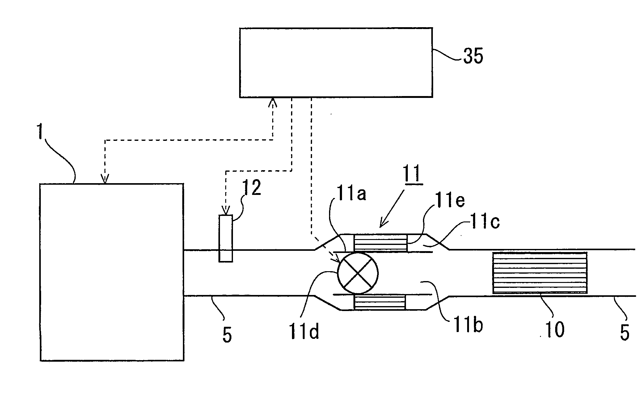
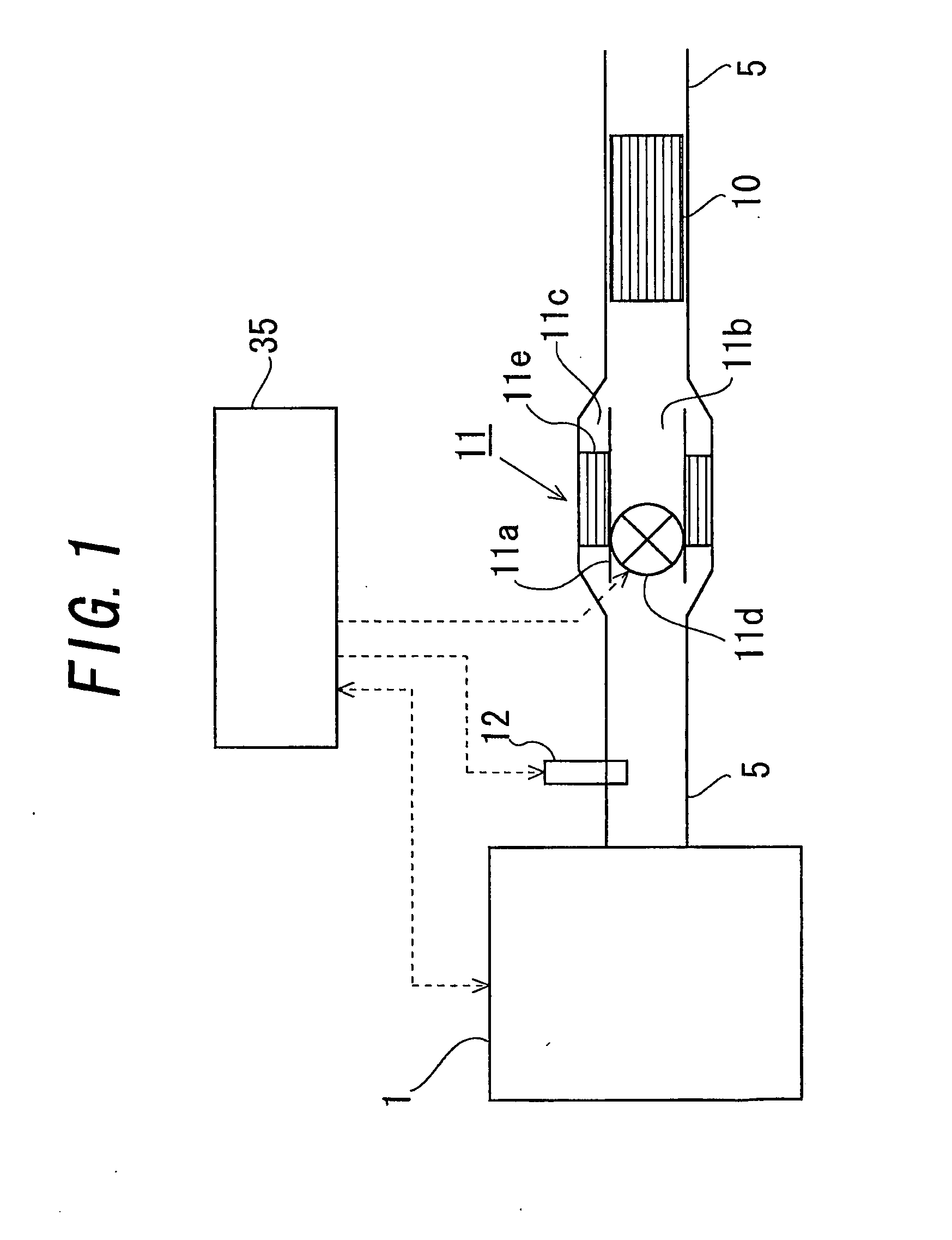
[0049]FIG. 1 is a view showing an internal combustion engine according to a first embodiment and showing outlines of configurations of an exhaust system and a control system thereof. An internal combustion engine 1 shown in FIG. 1 is classified as a diesel engine. Note that an interior of the internal combustion engine 1 and an intake system thereof are omitted in FIG. 1.

[0050]In FIG. 1, an exhaust pipe 5, through which an exhaust gas discharged from the internal combustion engine 1 flows, is connected to the internal combustion engine 1 and is further connected downstream to an unillustrated silencer. Moreover, an exhaust gas purifying device 10, which purifies the exhaust gas from NOx and particulate matters (e.g., soot), is disposed downstream in the exhaust pipe 5. Then, an exhaust gas temperature increasing device 11, which increases the temperature of the exhaust gas purifying device 10 by increasing a temperature of the exhaust gas flowing into the exhaust gas purifying devic...

second embodiment

[0080]Next, a second embodiment of the present invention will be described. The second embodiment will exemplify another configuration of the exhaust gas temperature increasing device 11 explained in FIG. 1.

[0081]FIG. 4 is a view showing an outline of the configuration of the exhaust gas temperature increasing device 11 in the second embodiment. A first mode of the second embodiment is that as illustrated in FIG. 4 (A), an exhaust gas purifying device 20 and an exhaust gas temperature increasing device 21 are substantially equalized in their diameters and are provided within a pipe having the same diameter. According to the first mode, the exhaust gas can be more smoothly flowed into the exhaust gas purifying device 20 without disturbing the flow of the exhaust gas discharged from the exhaust gas temperature increasing device 21. Further, especially when an oxidation catalyst 21e is provided in an external pipe portion 21c, the high-temperature exhaust gas discharged from the oxidat...


PUM


Abstract

An exhaust passageway of the internal combustion engine is formed of a single exhaust pipe 5. A portion 11b configuring a passageway through which the exhaust gas passes and a portion 11c provided with a catalyst 11e heating up the exhaust gas by emitting heat upon being supplied with a reducing agent, are provided in parallel so as to share a section of the single exhaust pipe with each other on an upstream side 11 of an exhaust gas purifying device 10 in the exhaust pipe 5. In the exhaust gas flowing through the exhaust pipe 5, allocation of a quantity of the exhaust gas passing through the catalyst 11e and a quantity of the exhaust gas passing through the passageway 11b, is set changeable.

Description

[0001]This is a 371 national phase application of PCT / JP2006 / 307008 filed 28 Mar. 2006, claiming priority to Japanese Patent Application No. JP 2005-091485 filed 28 Mar. 2005, the contents of which are incorporated herein by reference.FIELD OF THE INVENTION[0002]The present invention relates to an exhaust gas purifying system of an internal combustion engine.BACKGROUND OF THE INVENTION[0003]An exhaust gas from an internal combustion engine contains harmful substances such as NOx (nitrogen oxide). It is known that a NOx catalyst for purifying the exhaust gas of NOx is provided in an exhaust system of the internal combustion engine in order to decrease emissions of these harmful substances. In this technology, when a temperature of the NOx catalyst is low, there might be a case that a NOx purifying efficiency decreases. Accordingly, the temperature of the NOx catalyst needs increasing up to a temperature at which the exhaust gas can be sufficiently purified of NOx.[0004]On the other h...

Claims


Application Information

Patent Timeline
Patent Type & Authority Applications(United States)
IPC IPC(8): F01N3/20F01N3/025
CPCF01N3/0253F01N13/0097F01N3/2033F01N3/204F01N3/2053F01N2410/02F01N2410/04F01N2410/06F01N2410/12F02D41/1454F02D2200/0802Y02T10/26F01N13/009F01N13/011F01N3/0821Y02T10/12
Inventor SUGIYAMA, KOUSEKIODA, TOMIHISA
Owner TOYOTA JIDOSHA KK
Why Eureka
Try Eureka