Variable valvetrain turbocharged engine

a turbocharged engine and variable valvetrain technology, applied in the direction of valve drives, machines/engines, electric control, etc., can solve the problems of reducing fuel economy, reducing catalyst light-off times, and complex use of turbine bypass valves, so as to reduce catalyst inlet temperature significantly, accelerate catalyst warm-up, and extend the operating region of the engine

Active Publication Date: 2013-10-17
FORD GLOBAL TECH LLC
View PDF4 Cites 25 Cited by
  • Summary
  • Abstract
  • Description
  • Claims
  • Application Information

AI Technical Summary

Benefits of technology

[0002]Turbo charging an engine allows the engine to provide power similar to that of a larger displacement engine while engine pumping work is maintained near the pumping work of a normally aspirated engine of similar displacement. Thus, turbo charging can extend the operating region of an engine. However, turbocharged engines can have difficulty obtaining rapid catalyst light-off times after an engine start. The additional mass and surface area introduced by the turbine housing can reduce the catalyst inlet temperature significantly. Previous solutions to achieve rapid catalyst warm-up have relied on high heat flux combustion strategies and / or turbine bypass valves to increase the temperature of exhaust reaching the catalyst.
[0003]However, the inventors herein have recognized a few issues with the above approach. High heat combustion utilizes excess fuel, reducing fuel economy. Further, the use of turbine bypass valves can be complex and may pose sealing and high actuation force requirements.

Problems solved by technology

However, turbocharged engines can have difficulty obtaining rapid catalyst light-off times after an engine start.
However, the inventors herein have recognized a few issues with the above approach.
High heat combustion utilizes excess fuel, reducing fuel economy.
Further, the use of turbine bypass valves can be complex and may pose sealing and high actuation force requirements.

Method used


Image

  • Variable valvetrain turbocharged engine
  • Variable valvetrain turbocharged engine
  • Variable valvetrain turbocharged engine

Examples


Embodiment Construction

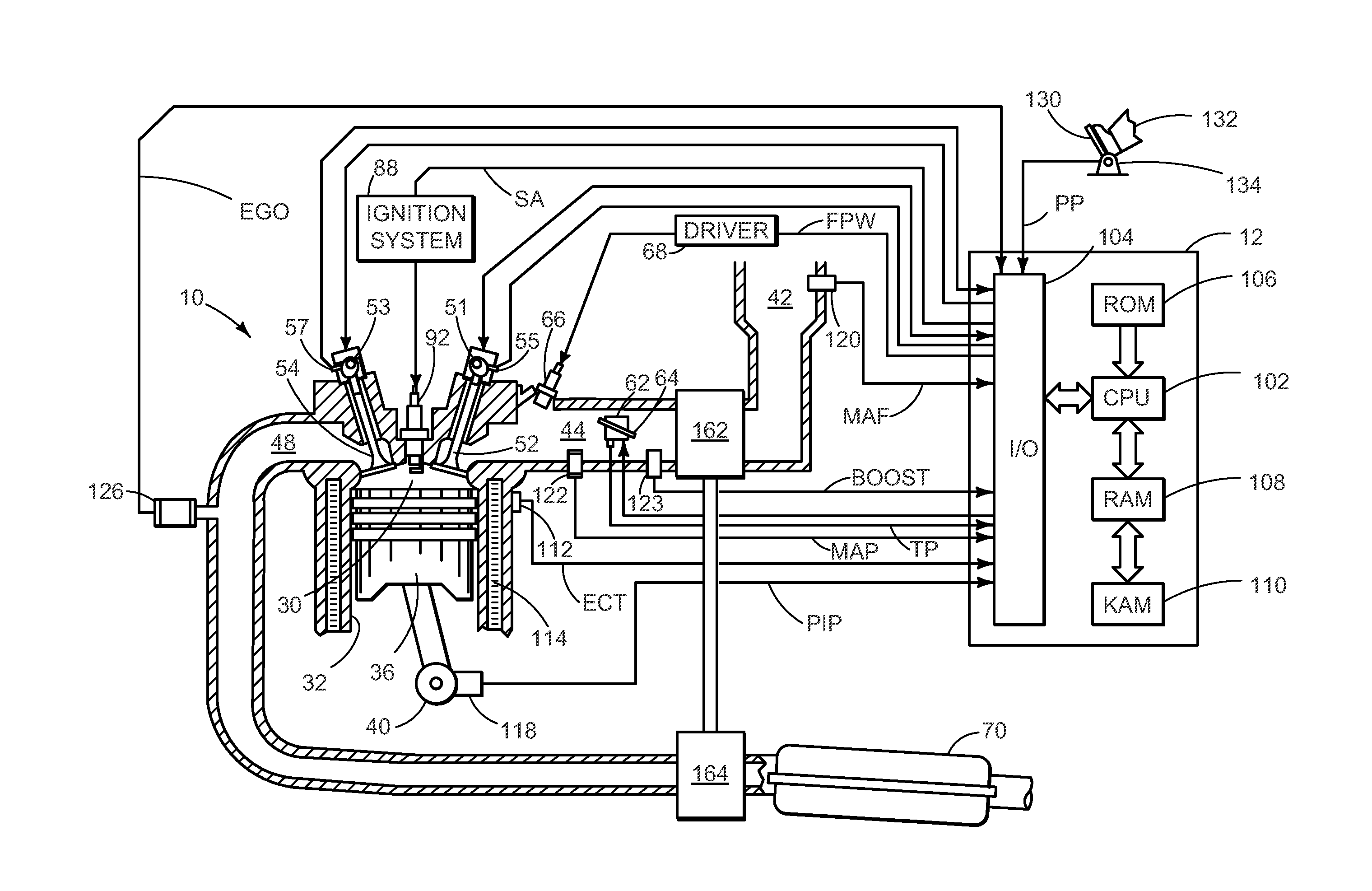
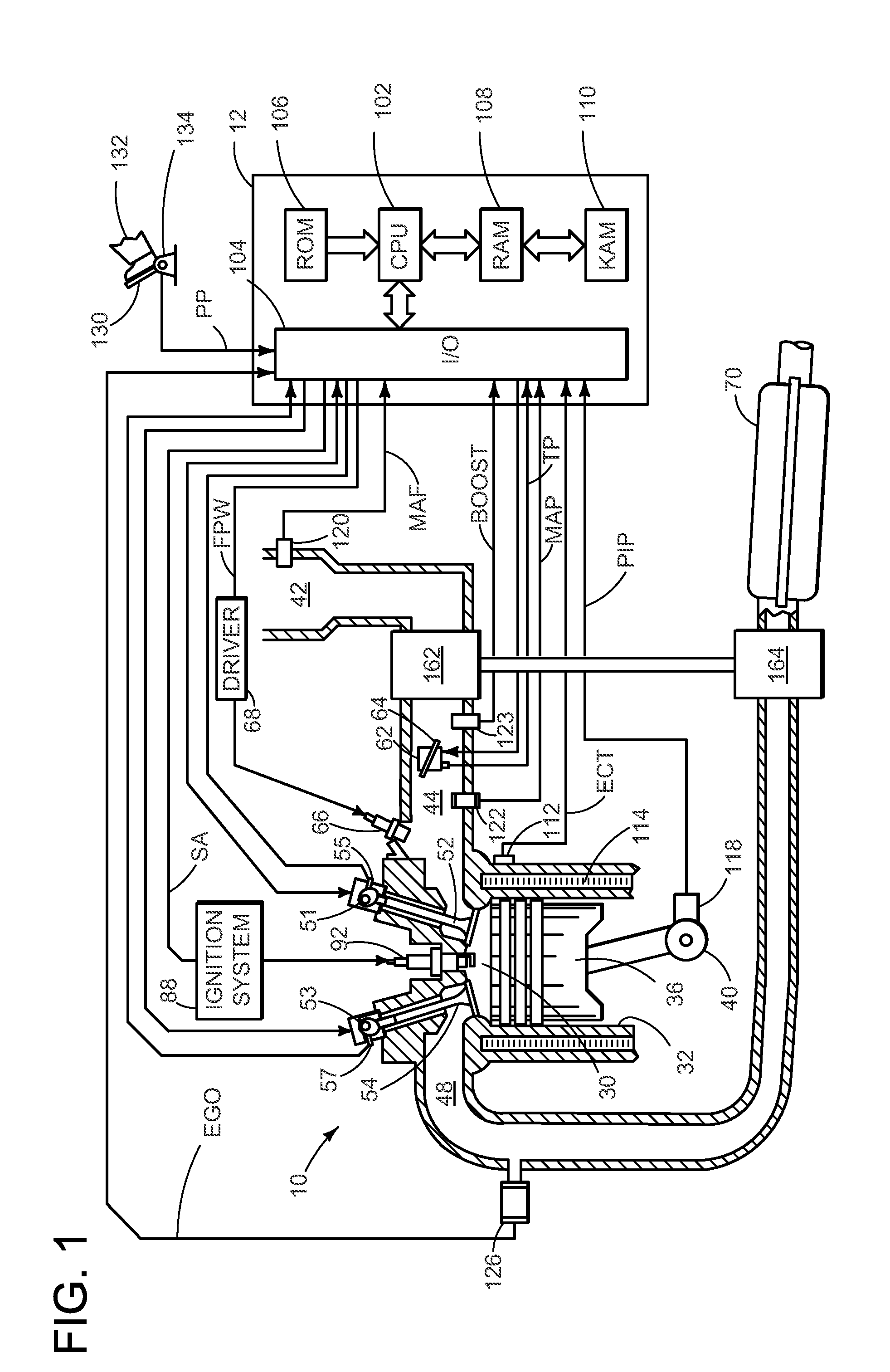
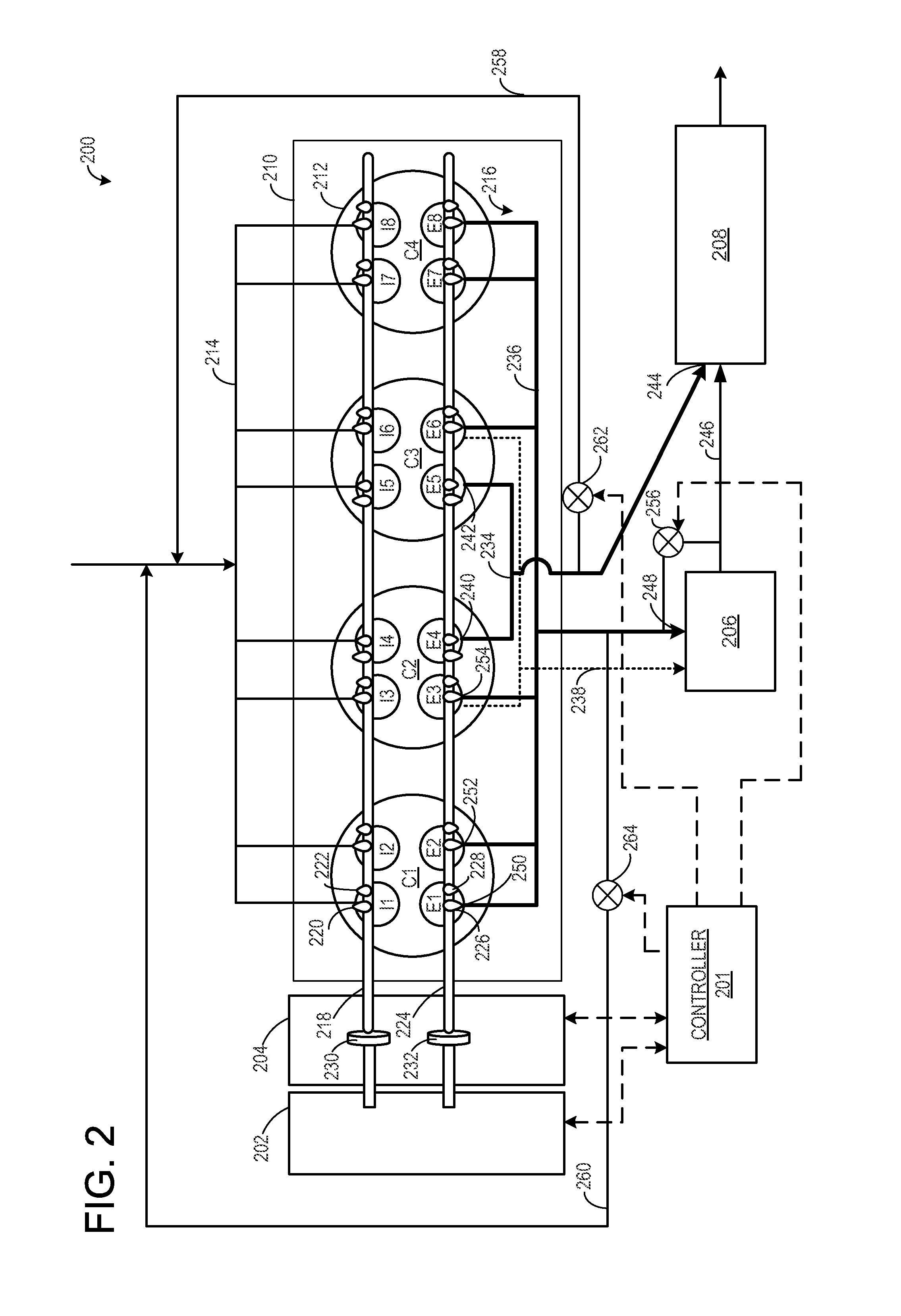
[0012]In turbocharged engines, exhaust is typically routed through the turbocharger before reaching one or more downstream exhaust components, such as catalysts. Traveling through the turbocharger may cool the exhaust, due to the additional surface area and longer exhaust path provided by the turbocharger, reducing the catalyst inlet temperature and increasing catalyst light-off time during cold engine starts. To increase catalyst inlet temperature under cold start conditions, a cam profile switching system may be combined with a segmented integrated exhaust manifold and variable displacement engine (VDE) operation to provide a direct, shortened exhaust path to the catalyst. For example, in an inline four cylinder engine, the inner cylinders may each have one exhaust port coupled directly to the catalyst and one exhaust port directly coupled to the turbocharger, via separate exhaust manifolds, while the outer cylinders may only be coupled to the turbocharger. During cold start condi...


PUM


Abstract

Embodiments for routing exhaust in an engine are provided. In one example, an engine method comprises, during a first condition, firing a subset of cylinders and routing all exhaust from the subset of cylinders through a first exhaust manifold coupled directly to a catalyst and not a turbocharger, and during a second condition, firing all cylinders, routing a first portion of exhaust through a second exhaust manifold coupled to the turbocharger, and routing a second portion of exhaust through the first exhaust manifold. In this way, exhaust can be directly routed to a catalyst under some conditions.

Description

FIELD[0001]The present disclosure relates to a camshaft profile switching system in an engine.BACKGROUND AND SUMMARY[0002]Turbo charging an engine allows the engine to provide power similar to that of a larger displacement engine while engine pumping work is maintained near the pumping work of a normally aspirated engine of similar displacement. Thus, turbo charging can extend the operating region of an engine. However, turbocharged engines can have difficulty obtaining rapid catalyst light-off times after an engine start. The additional mass and surface area introduced by the turbine housing can reduce the catalyst inlet temperature significantly. Previous solutions to achieve rapid catalyst warm-up have relied on high heat flux combustion strategies and / or turbine bypass valves to increase the temperature of exhaust reaching the catalyst.[0003]However, the inventors herein have recognized a few issues with the above approach. High heat combustion utilizes excess fuel, reducing fue...

Claims


Application Information

Patent Timeline
Patent Type & Authority Applications(United States)
IPC IPC(8): F02B27/04F01L1/04
CPCF01L2001/0537F01L2001/34496F01N3/2006F01N13/107F01N2240/36F01N2260/08F02B37/02F02B37/18F02D13/0207F02D13/0257F02D13/06F02D41/0007F02D41/0245F02D41/0255F02D41/064F02D2041/001F02D2200/021F02D2200/101F02P5/1506F02P5/1512F02P5/1516F02M26/05F02M26/38F02M26/42Y02T10/12Y02T10/40F01N2430/02
Inventor ERVIN, JAMES DOUGLASKU, KIM HWEMCCONVILLE, GREGORY PATRICKBOYER, BRAD ALAN
Owner FORD GLOBAL TECH LLC
Why Eureka
Try Eureka