Arrangement For Controlling Exhaust Pressure Pulses At An Internal Combustion Engine

a technology of exhaust pressure and combustion engine, which is applied in the direction of electric control, machines/engines, mechanical equipment, etc., can solve the problems of more or less constant active, entail complications, and process takes a relatively long time, so as to prevent the effect of adverse effects of fuel in the egr circuit, less manufacturing cost, and more space for installation

Active Publication Date: 2008-05-15
VOLVO LASTVAGNAR AB
View PDF0 Cites 26 Cited by
  • Summary
  • Abstract
  • Description
  • Claims
  • Application Information

AI Technical Summary

Benefits of technology

[0002]The diesel engine is known for operational reliability and low fuel consumption but does not produce as low emissions as, for example, a petrol engine provided with a three-way catalyst. One way of improving the emissions from a diesel engine is to fit a particle filter which filters soot and particles from the exhaust gases and / or the NOx post-treatment system. These filters are usually very effective and gather both large and small particles. To prevent the filter from becoming full of soot and causing a major pressure drop for the exhaust gases leaving the engine, the soot has to be burnt. One method is for this soot to be burnt by the nitrogen oxides contained in diesel exhaust gases. In that case, the portion of the nitrogen oxides that takes the form of NO2 can oxidise the soot within the temperature interval of about 250 to 400° C., but this process takes a relatively long time and needs to be more or less constantly active even if there is an oxidation catalyst before the filter or the filter itself is covered with a catalytic layer. Another method for oxidising soot accumulated in the particle filter is to heat the filter to about 600-650° C. so that the surplus oxygen O2 from diesel combustion can oxidise the soot directly, which is a rapid process. Soot accumulated over many hours of operating time can be oxidised away in a time of the order of 5 to 10 minutes. The exhaust temperature of a diesel engine normally never reaches 600-650° C., particularly after a turbo unit whereby the turbine extracts power from the exhaust flow and causes a temperature drop. It is not unusual that the exhaust temperature after the turbine of the turbo unit is often lower than 250° C., a temperature (tit which an oxidation catalyst does not function. There are various special measures for temporarily increasing the exhaust temperature of a diesel engine.
[0006]These adverse effects due to fuel in the EGR circuit can be prevented either by closing the EGR circuit when late post-injection takes place, or alternatively, as a consequence of the NOx level increasing from the combustion, applying late post- combustion only in carefully selected cylinders in combination with designing the exhaust manifold in such a way that EGR gases are only taken from cylinders which have no late post- injection. U.S. Pat. No. 5,987,884 and U.S. Pat. No. 6,141,959 describe how an exhaust system divided into two portions, combined with late post-injection in certain designated cylinders, to avoid the above problems caused by fuel in the EGR circuit. The method of dividing an exhaust system into two portions usually means that the exhaust system is more expensive to manufacture and requires more space for installing it.
[0007]It is desirable to provide an arrangement in a combustion engine which avoids the effects on the flow in the EGR circuit which are caused by means for regeneration of an exhaust post-treatment unit situated in the exhaust system even in the case of exhaust systems in which all the exhaust gases are collected in one and the same duct entirely outside the exhaust ports of each cylinder. It is also desirable to provide uniform pressure pulses at both the exhaust outlet of the exhaust manifold and its EGR outlet.

Problems solved by technology

The diesel engine is known for operational reliability and low fuel consumption but does not produce as low emissions as, for example, a petrol engine provided with a three-way catalyst.
In that case, the portion of the nitrogen oxides that takes the form of NO2 can oxidise the soot within the temperature interval of about 250 to 400° C., but this process takes a relatively long time and needs to be more or less constantly active even if there is an oxidation catalyst before the filter or the filter itself is covered with a catalytic layer.
Combining this system with particle filters and / or NOx post-treatment by so-called NOx trap or NOx catalyst entails complications.
When it is desired to adopt measures intended, for example, to increase the temperature of the exhaust flow, there is no point in increasing the exhaust temperature in the EGR flow, since it has to pass through the EGR cooler, whereupon the increased exhaust heat increases the load on the EGR cooler without being used in any positive way but resulting rather in the fuel consumption being somewhat increased due to the increase in the exhaust temperature.
When the engine's operating mode subsequently changes and the gas flow changes, the liquid accumulated may possibly accompany the gas flow momentarily and immediately enter one or more cylinders in an uncontrolled manner.
This gives rise to uncontrolled behaviour of the engine and may cause serious accidents and / or damage.
Even a small leak in the EGR circuit may become very obvious if condensed fuel begins to trickle out through the leak.
The method of dividing an exhaust system into two portions usually means that the exhaust system is more expensive to manufacture and requires more space for installing it.

Method used


Image

  • Arrangement For Controlling Exhaust Pressure Pulses At An Internal Combustion Engine
  • Arrangement For Controlling Exhaust Pressure Pulses At An Internal Combustion Engine
  • Arrangement For Controlling Exhaust Pressure Pulses At An Internal Combustion Engine

Examples


Embodiment Construction

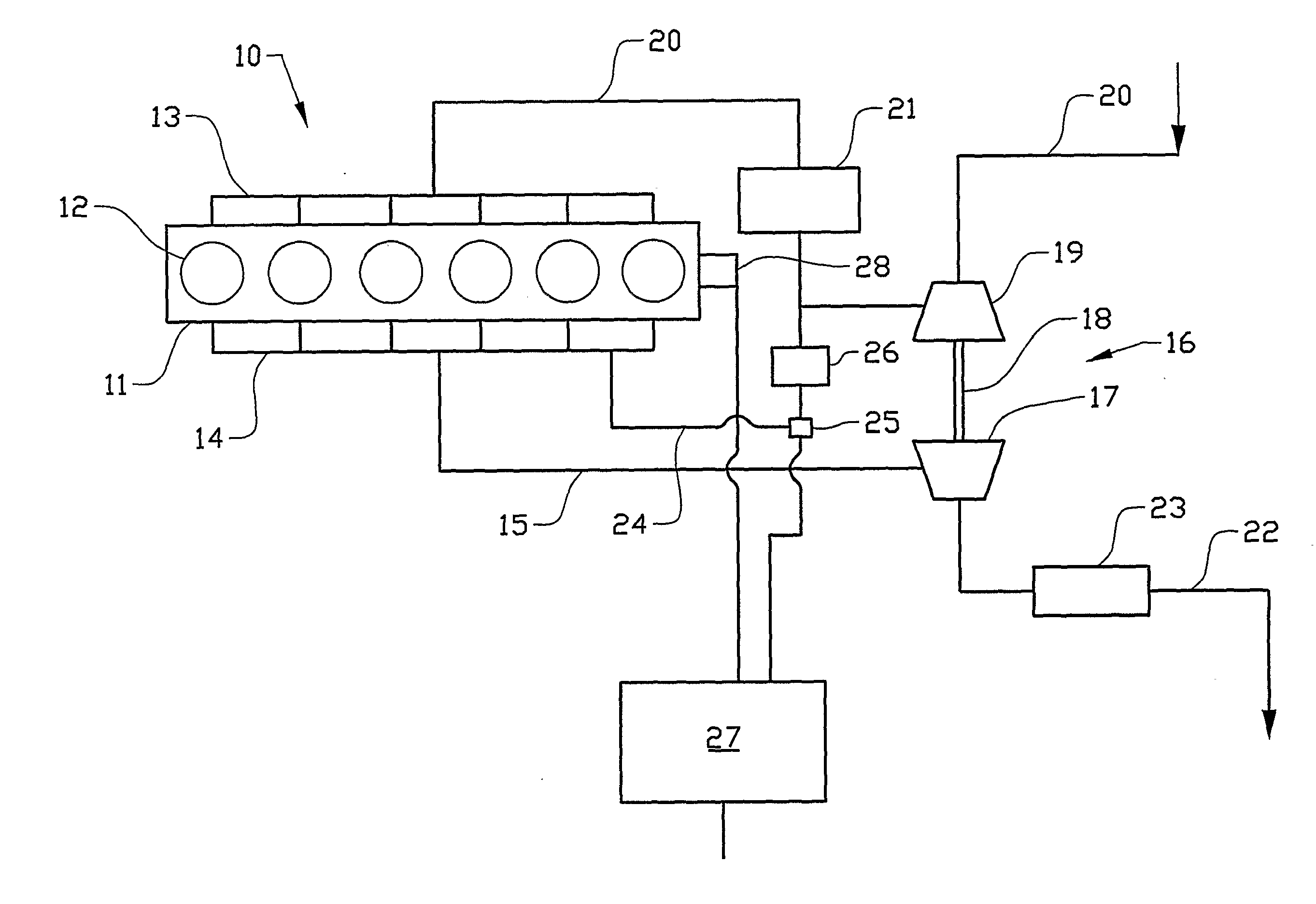
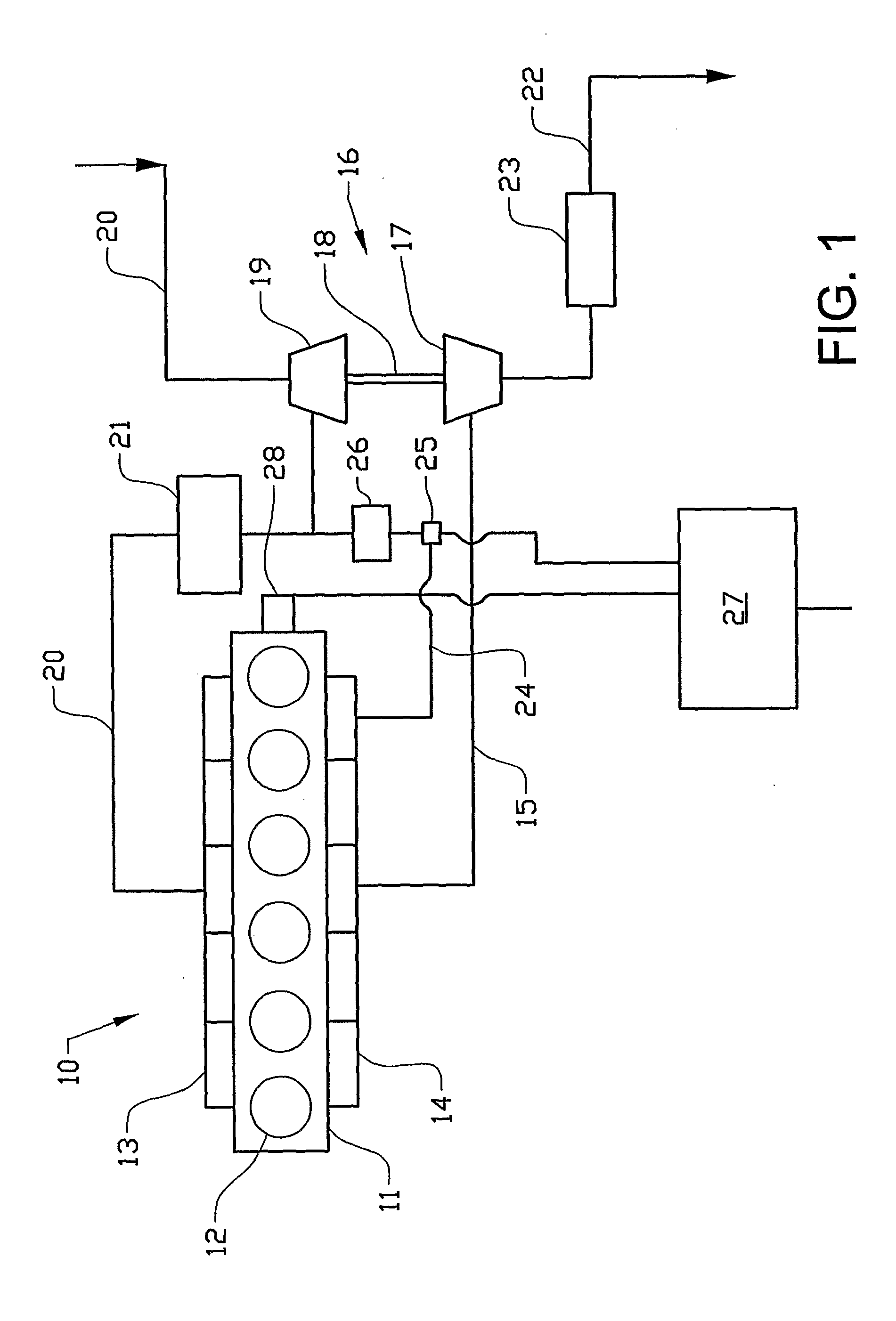
[0014]The combustion engine 10 schematically depicted in FIG. 1 comprises an engine block 11 with six piston-cylinders 12 with an inlet manifold 13 and an exhaust manifold 14. Exhaust gases are led via an exhaust passage 15 to the turbine wheel 17 of a turbo unit 16. The turbine shaft 18 drives the compressor wheel 19 of the turbo unit that compresses air coming in via an inlet passage 20 and passes it on via a charge air cooler 21 to the inlet manifold 13. Fuel is supplied to the respective cylinders 12 via (undepicted) injection devices.

[0015]Exhaust gases which have passed through the turbine unit 16 are led to the atmosphere via the exhaust line 22, which leads the exhaust gases through a regenerable device for exhaust post-treatment, e.g. a particle trap or NOx trap 23. Regeneration of the particle trap is effected by supply of unburnt fuel from any of the cylinders 12, e.g. by so-called “post-injection”, which by oxidation of the fuel in the catalyst upstream from the particle...


PUM


Abstract

An arrangement for controlling exhaust pressure pulsation in a combustion engine including six cylinders. The engine also includes an inlet for supply of air to the cylinders, and an exhaust manifold for delivery of exhaust gases from the cylinders. The manifold is provided with a first outlet to an exhaust system and with a second outlet to a conduit for feeding exhaust gases back, via an EGR circuit, from at least one of the engine's cylinders to the inlet. At least one of the cylinders is adapted to enrich the exhaust gases with unburnt hydrocarbon with a view to regeneration of an exhaust gas post-treatment unit situated in the exhaust system. A special configuration of the exhaust manifold results in separation of regeneration gas from EGR gas in the exhaust manifold.

Description

BACKGROUND AND SUMMARY[0001]The present invention relates to an arrangement for control of exhaust pressure pulsation of a combustion engine.[0002]The diesel engine is known for operational reliability and low fuel consumption but does not produce as low emissions as, for example, a petrol engine provided with a three-way catalyst. One way of improving the emissions from a diesel engine is to fit a particle filter which filters soot and particles from the exhaust gases and / or the NOx post-treatment system. These filters are usually very effective and gather both large and small particles. To prevent the filter from becoming full of soot and causing a major pressure drop for the exhaust gases leaving the engine, the soot has to be burnt. One method is for this soot to be burnt by the nitrogen oxides contained in diesel exhaust gases. In that case, the portion of the nitrogen oxides that takes the form of NO2 can oxidise the soot within the temperature interval of about 250 to 400° C....

Claims


Application Information

Patent Timeline
Patent Type & Authority Applications(United States)
IPC IPC(8): F02M25/07F01N3/025F01N3/035F01N3/10F02B37/00F01N13/10F01N13/08
CPCF01N3/023F01N3/0871F01N13/10F02B29/0406F02D41/0065F02D41/0082Y02T10/146F02M25/0707F02M25/0727F02M25/0746F02M25/0748Y02T10/121F02D41/027F02M26/40F02M26/05F02M26/23F02M26/42Y02T10/12
Inventor PERSSON, PER
Owner VOLVO LASTVAGNAR AB
Why Eureka
Try Eureka