Continuous extruder with supporting roll

A technology of supporting rollers and extrusion machines, which is applied in the manufacture of electrical components, circuits, cables/conductors, etc., can solve the problems of long extruded metal runners, large diameters of extrusion wheels 20, and difficulty in arranging, so as to achieve uniform heating, The effect of reducing the chance of thermal fatigue damage and improving safety

Active Publication Date: 2010-05-26
大连康丰科技有限公司
View PDF0 Cites 3 Cited by
  • Summary
  • Abstract
  • Description
  • Claims
  • Application Information

AI Technical Summary

Problems solved by technology

[0009] For continuous cladding, due to the large diameter of the extrusion wheel 20, it is difficult to arrange the working part of

Method used


Image

  • Continuous extruder with supporting roll
  • Continuous extruder with supporting roll
  • Continuous extruder with supporting roll

Examples


Example Embodiment

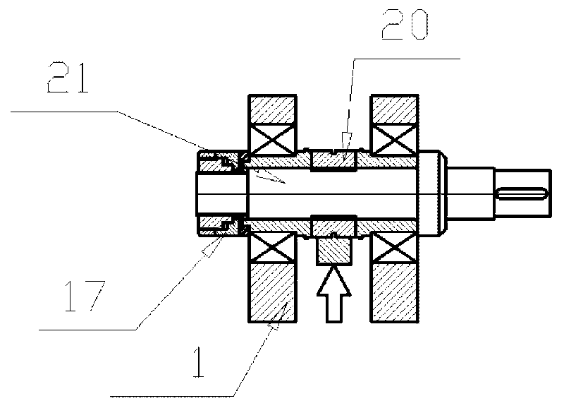
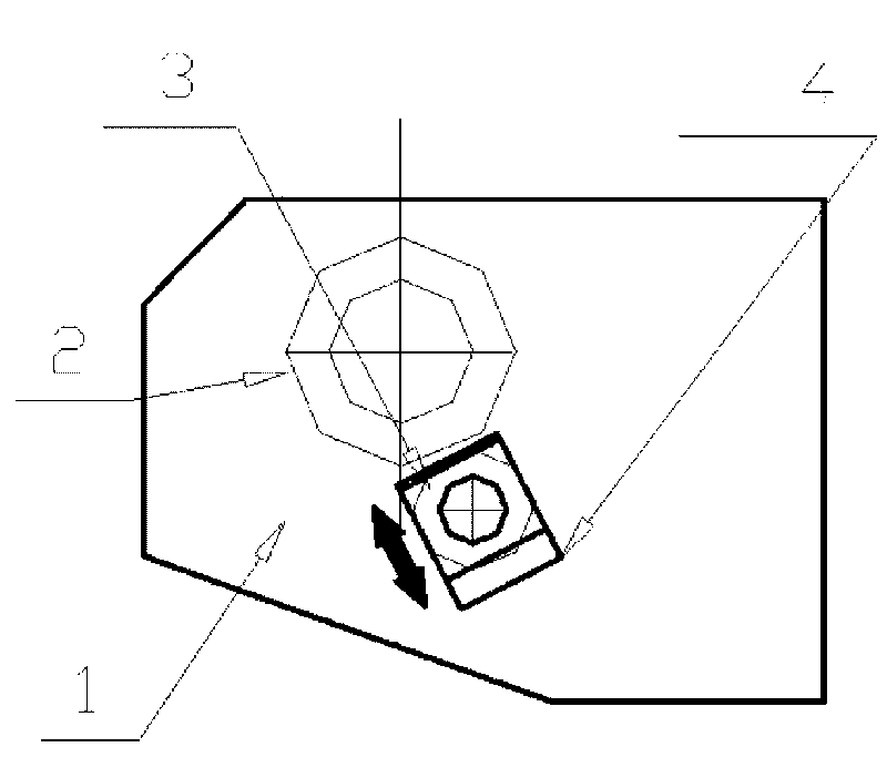
[0029] like image 3 Shown is a continuous extruder with a support roller, which involves a die head mechanism. The frame 1 is equipped with a squeeze roller 10 and a die cavity 9. The frame 1 is provided with a chute 4, and the chute 4 passes through the bearing. The seat 3 is installed with a squeeze roller 10, while a support roller 2 is installed in the chute, the load 16 is applied to the squeeze roller 10, and the support roller 2 is arranged in the opposite direction to the load 16 and supported on the surface of the squeeze roller 10, squeezed The roller 10 and the support roller 2 are in pressing contact, and the hydraulic cylinder drives the connection of the cavity preload block 8, the cavity preload block 8 preloads the mold cavity 9 and the extrusion roller 10, and maintains a proper gap between the mold cavity and the extrusion roller constant.

[0030] The mold 13 is installed in the mold cavity 9 of the present invention, and the mold adopts an extrusion mold ...


PUM


Abstract

The invention relates to continuous extruding and cladding equipment. A continuous extruder with a supporting roll is characterized in that a stander is provided with an extruding roll and a die cavity, the stander is provided with a chute, the extruding roll and the supporting roll are arranged in the chute, a load is applied to the extruding roll, the supporting roll is arranged in the direction opposite to the load and supported on the surface of the extruding roll, and the extruding roll and the supporting roll are in compact contact. In the continuous extruder with the supporting roll, the radial load of the extruding roll can be borne by the supporting roll, so the diameter of the extruding roll is much smaller compared with that of the conventional extruding wheel, the extruding roll is much longer, the axis of the extruding wheel is simplified, and the operation of the equipment and the running safety are greatly improved. The extruding roll belongs to an easily-damaged part of tools; and because of great reduction of the size, the using cost is correspondingly reduced.

Description

Technical field: [0001] The invention belongs to the fields of non-ferrous metal processing and cable manufacturing, and relates to equipment for continuous extrusion and continuous coating. Background technique: [0002] The main shaft of the existing continuous extrusion press adopts the bearing direct support structure, see figure 1 , 2 . Due to the large torque and extrusion load to be transmitted, the diameter of the spindle also needs to be large. In order to solve the contradiction between the easy failure of the working part of the main shaft and the large size and high cost, the main shaft is designed as a composite structure, that is, the working part is designed as a ring, which is called the extrusion wheel 20, and then the shaft sleeve and other parts are serially sleeved on the mandrel. 21, and then clamped by the hydraulic nut 17. In this way, when failure and damage occur, only the pressing wheel 20 can be replaced. [0003] The downside of this structur...

Claims


Application Information

Patent Timeline
IPC IPC(8): H01B13/24B21C23/21
Inventor 樊志新宋宝韫
Owner 大连康丰科技有限公司
Why Eureka
Try Eureka