Guide slide mechanism of vehicle-mounted accumulator box

A vehicle-mounted battery box, guide sliding technology, applied to battery pack parts, locomotives, circuits, etc., can solve problems affecting inspection efficiency, tipping, battery box 1 instability, etc.

Inactive Publication Date: 2010-05-26
CHANGSHU DECHANG AUTOMOBILE TOOLS
View PDF0 Cites 11 Cited by
  • Summary
  • Abstract
  • Description
  • Claims
  • Application Information

AI Technical Summary

Problems solved by technology

[0004] There are the following deficiencies in the guide sliding mechanism of the vehicle load battery box of the above structure: First, although the two ends of the battery box 1 can be limited by the locking member 5, they will not move left and right in the battery box cavity 2, but the length of the battery box 1 Because the two sides of the direction cannot be controlled by the corresponding components, there is a phenomenon of swaying back and forth when the fast-running train turns or other similar situations, and it hits the cavity wall of the battery box cavity 2, causing the cavity wall to deform, especially the battery box. The electrolyte in the battery (bottle) in 1 will escape from the battery and pollute the battery box 1, causing corrosion to the battery box 1; the second is that the extent to which the battery box 1 is moved out of the battery box cavity 2 is limited, and the battery box 1 cannot be removed. Move out under the state of keeping stable and without bumps all the time, because there is a vacant transition area (gap) between the cavity door 4 and the cavity opening of the battery box cavity 2 or the cavity cavity, when the roller 11 moves from the guide device 3 When transitioning to the chamber door 4, one end of the battery box 1 needs to be lifted up by manpower, otherwise the roller 11 will hang in the aforementioned transition area, that is, the gap, so the labor intensity of the inspection personnel is relatively high and affects the inspection efficiency , and, for the convenience of inspection, if the battery box 1 is pulled out transitionally, it will cause the battery box 1 to become unstable, or even tip over (rollover), so the battery box 1 is moved out of the battery box cavity 2 It must be restrained, but the smaller the degree of removal, the less convenient it is for the staff to check or replace the battery located at the right end of the battery box 1

Method used


Image

  • Guide slide mechanism of vehicle-mounted accumulator box
  • Guide slide mechanism of vehicle-mounted accumulator box
  • Guide slide mechanism of vehicle-mounted accumulator box

Examples


Embodiment Construction

[0016] In order to enable the examiners of the patent office, especially the public, to understand the technical essence and beneficial effects of the present invention more clearly, the applicant will describe in detail below in conjunction with the accompanying drawings in the form of embodiments, but none of the descriptions of the embodiments is a description of the present invention. Restriction of the inventive solution, any equivalent transformation made according to the concept of the present invention which is only in form but not in substance shall be regarded as the scope of the technical solution of the present invention.

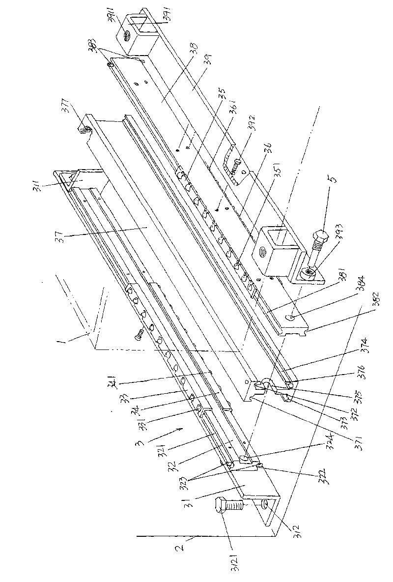
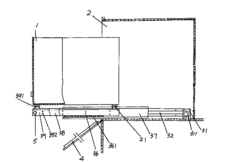
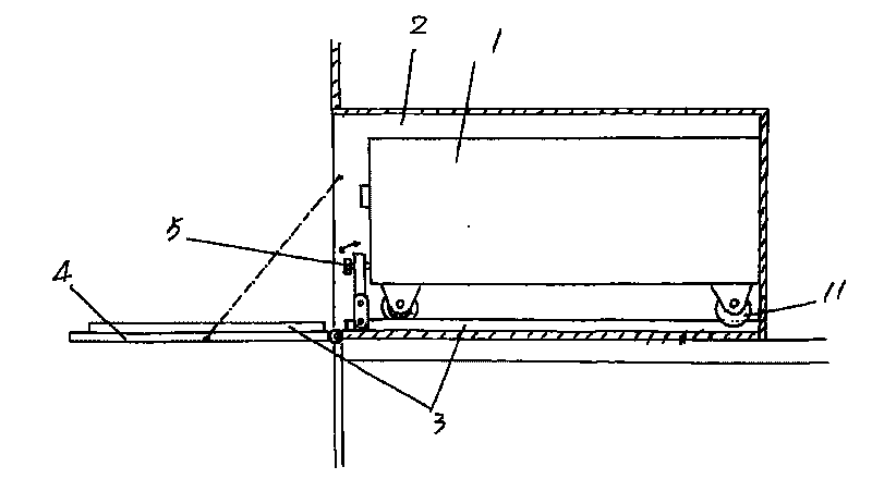
[0017] please see figure 1 , the preset battery box cavity 2 of the outer bottom of the train (train) compartment is provided, and a vehicle-mounted battery box provided by the present invention is respectively arranged on the corresponding two sides of the bottom of the length direction of the battery box cavity 2 Guide slide mechanism, in f...


PUM


Abstract

The invention relates to a guide slide mechanism of a vehicle-mounted accumulator box, which belongs to the technical field of vehicle facilities. The guide slide mechanism of a vehicle accumulator box comprises a pair of guide devices for the accumulator box, wherein the guide device are laid on the bottom in the length direction of the accumulator box cavity of the train in parallel; each guide device comprises a fixed seat, a fixed slide bar, first, second, third and fourth steel ball locating racks respectively provided with a steel ball, a first and second movable slide bars and a box body fixing plate. In overhaul and maintenance, the technical scheme can reduce the labor intensity of the operators, and can prevent the electrolyte in the accumulator from overflow to pollute the accumulator box in the operating state.

Description

technical field [0001] The invention belongs to the technical field of vehicle facilities, and in particular relates to a guide sliding mechanism for a vehicle-mounted battery box, which is arranged on the outer bottom of a train carriage, and is used for the battery box equipped on the outer bottom of the carriage to carry the battery in the battery box out or Reply. Background technique [0002] As known in the industry, the bottom (outer bottom) of each compartment of trains, especially passenger trains, is respectively equipped with at least one battery box, and batteries are arranged in each battery box, and batteries are such as lead-acid batteries or lithium batteries, so that Power supply for train lighting, watching TV and broadcasting, etc. [0003] image 3 The schematic diagram of the guide sliding mechanism of the vehicle-mounted battery box in the prior art is shown. The rollers 11 arranged at the bottom of both sides in the length direction of the battery box...

Claims


Application Information

Patent Timeline
Patent Type & Authority Applications(China)
IPC IPC(8): H01M2/10B61C17/00H01M50/264
CPCY02E60/12Y02E60/10
Inventor 顾善昌
Owner CHANGSHU DECHANG AUTOMOBILE TOOLS
Why Eureka
Try Eureka