
Novel centrally-arranged switch cabinet grounding device

A grounding device and switchgear technology, applied in the direction of the grounding device of the switchgear, etc., can solve the problems of not easy to observe, inconvenient on-site operation, easy to forget to restore the grounding wire, etc.

Inactive Publication Date: 2010-05-26
上海广浩电器有限公司
View PDF6 Cites 5 Cited by
  • Summary
  • Abstract
  • Description
  • Claims
  • Application Information

AI Technical Summary

Problems solved by technology

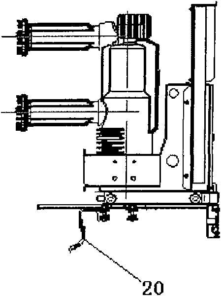
However, in the actual use process, some shortcomings were also found: the grounding bar of the cabinet is installed on the intermediate partition at the bottom of the handcart, and the grounding bar is connected to the general grounding of the cabinet by a copper braided wire 20, while the switch cabinet is installed, During maintenance, it is often necessary to pull out the middle partition, which can only be pulled out by untying the braided wire 20, which is very inconvenient for on-site operations, and it is easy to forget to restore the ground wire, which brings hidden dangers to the safe operation of the equipment; with the extensive use of large-capacity switches, Switches or isolation handcarts above 4000A need forced air cooling, generally use a fan at the bottom of the handcart, and the position of the grounding bar overlaps with the position of the fan
Since the grounding row is at the bottom of the handcart, it is not easy to observe whether the contact is good or not

Method used


Image

  • Novel centrally-arranged switch cabinet grounding device
  • Novel centrally-arranged switch cabinet grounding device
  • Novel centrally-arranged switch cabinet grounding device

Examples


Embodiment Construction

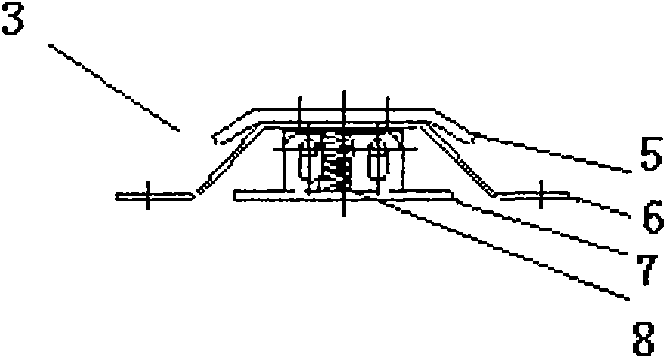
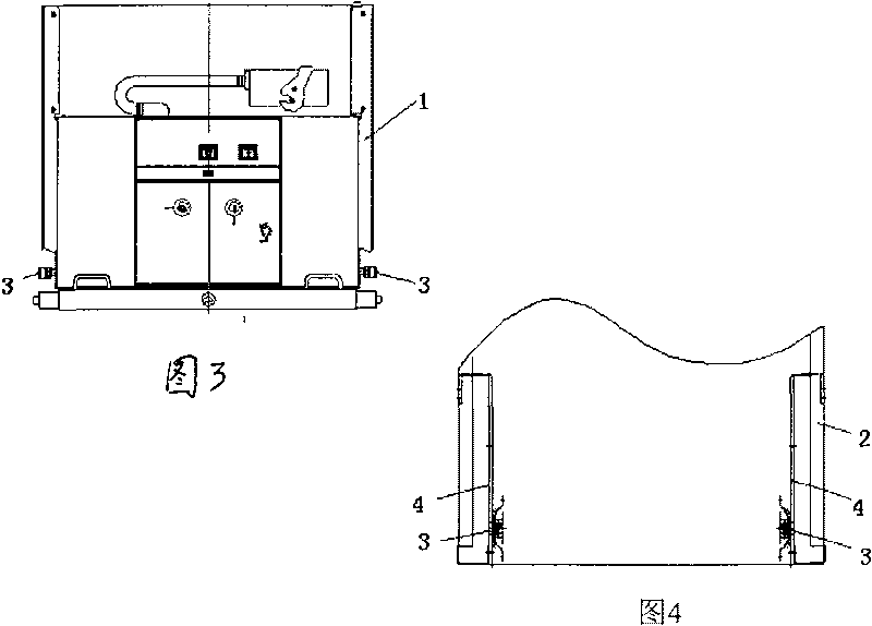
[0009] The figure includes a handcart 1 and a switch cabinet 2, which are characterized in that: there is a grounding device 3 on both sides of the lower part of the handcart 1, and the grounding devices on both sides of the inner side of the switch cabinet 2 and the lower two sides of the handcart 1 3 has a grounding copper bar 4 opposite. The grounding device 3 is composed of a thick copper bar 5, a copper strip 6, a fixed bracket 7 and a pressure spring 8. The pressure spring 8 is located in the fixed bracket 7, and the bottom of the fixed bracket 7 is connected to the handcart 1. There is an isosceles Trapezoidal copper strip 6, the inner side of the copper strip 6 is in conflict with the pressure spring 8, the bottom of both ends of the copper strip 6 is connected to the body of the handcart 1, and the outer side of the copper strip 6 is covered with a bow-shaped thick copper bar 5.

[0010] When in use, when the handcart 1 is pushed into the switch cabinet 2, the groundi...


PUM


Abstract

The invention relates to a novel centrally-arranged switch cabinet grounding device which comprises a handcart and a switch cabinet and is characterized in that a grounding device is respectively arranged at two sides of the lower part of the handcart, and grounding copper bars are arranged on two surfaces of the inner side of the switch cabinet opposite to the grounding devices at the two sides of the lower part of the handcart. The grounding devices comprise thick copper bars, copper belts, fixed brackets and pressure springs, wherein the pressure springs are arranged in the fixed brackets; the bottoms of the fixed brackets are connected with the handcart; the copper belts which are in an isosceles trapezoid are arranged on the fixed brackets; the inner sides of the copper belts are in contact with the pressure springs; the bottoms of the two ends of the copper belts are connected with the body of the handcart; and the thick copper bars which are folded into an arch form are coated outside the copper belts. The invention has the advantage that the two sides of the grounding devices are uniformly stressed symmetrically to perform a guiding function when the handcart moves inwards or outwards, so that the handcart can operate more stably and smoothly in the cabinet. The novel grounding device overcomes the defects and the disadvantages of the traditional grounding device and successfully passes the grounding loop test of the national laboratory.

Description

technical field [0001] The invention relates to a grounding device for a switch cabinet, in particular to a novel middle-mounted grounding device for a switch cabinet. Background technique [0002] In the current central switch cabinet, the connection between the handcart body and the general ground of the system mostly adopts the bottom friction grounding method (see Figure 1 ). This grounding method overcomes the shortcomings of the previous welding cabinets, such as difficulty in grounding and poor interchangeability, and greatly enhances the reliability and continuity of the grounding of the central switch cabinet. However, in the actual use process, some shortcomings were also found: the grounding bar of the cabinet is installed on the middle partition at the bottom of the handcart, and the grounding bar is connected to the general grounding of the cabinet by copper braided wire 20, while the switch cabinet is installed, During maintenance, it is often necessary to pu...

Claims


Application Information

Patent Timeline
Patent Type & Authority Applications(China)
IPC IPC(8): H02B11/28
Inventor 吴卫国
Owner 上海广浩电器有限公司
Learn More