Eureka AIR delivers breakthrough ideas for toughest innovation challenges, trusted by R&D personnel around the world.

Method for producing polysilicon rod

A manufacturing method and technology of polysilicon rods, which are applied in the fields of solar energy and semiconductors, can solve the problems of high equipment and operation requirements, and achieve the effect of promoting mass transfer, promoting mass transfer, and not increasing maintenance costs

Inactive Publication Date: 2010-06-02
JIANGSU ZHONGNENG POLYSILICON TECH DEV
View PDF1 Cites 12 Cited by
  • Summary
  • Abstract
  • Description
  • Claims
  • Application Information

AI Technical Summary

Problems solved by technology

However, the EFG (Edge Defined FilmFeed) method must be used to prepare such hollow silicon tubes. Compared with conventional polysilicon manufacturers using silicon mandrel furnaces to prepare heating elements, additional equipment and devices are required, and the outer diameter is so large The preparation of hollow silicon tubes has high requirements for equipment and operation

Method used

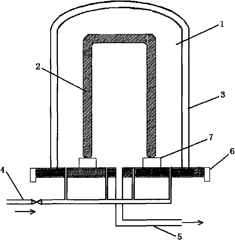
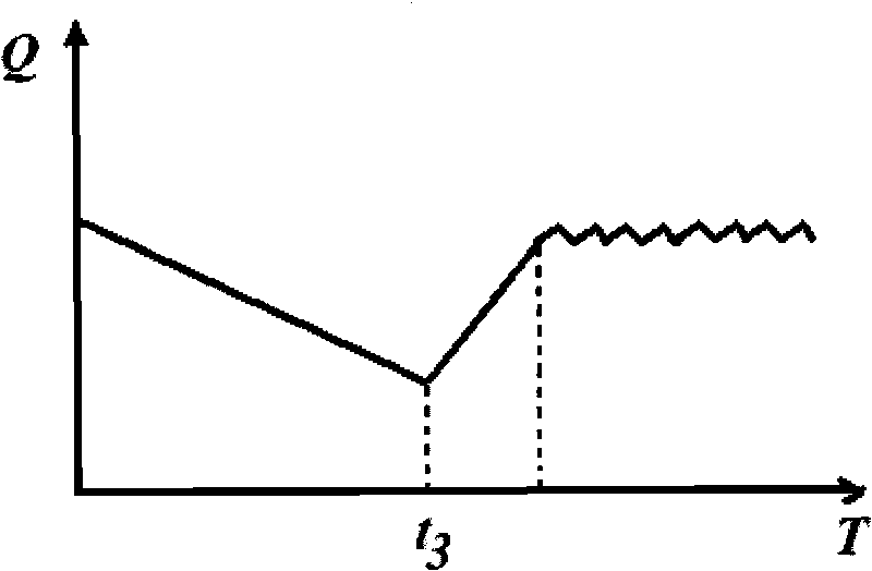
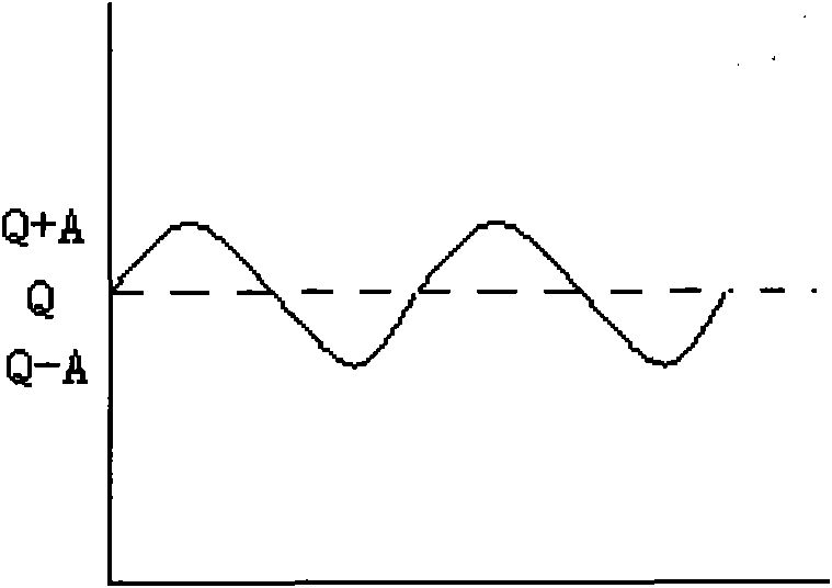

Image

  • Method for producing polysilicon rod
  • Method for producing polysilicon rod
  • Method for producing polysilicon rod

Examples


Embodiment 1

[0107] In this embodiment, the reaction pressure in the reduction furnace is controlled at 0.3 MPa, and the reaction temperature is controlled at 1080°C.

[0108] At the beginning (0 moment) of the manufacturing method, hydrogen and trichlorosilane are respectively charged at 35.8Nm 3 / h and 5.5Nm 3 The intake air of / h is continuously fed into the reduction furnace. At this time, the molar ratio Q value was 6.5.

[0109] First, use the time of 45 hours to make the molar ratio Q with the above expression of the aforementioned first-order piecewise function (wherein the a value, b value, c value and d value of the first-order piecewise function expression are passed according to the aforementioned in the specification sheet) Determined by calculation method, omitted here, the same below) continuously changes to 2.5, at the same time, within the aforementioned range, the intake flow rate of hydrogen and trichlorosilane increases linearly and continuously with the deposition ti...

Embodiment 2

[0128] In this example, the reaction pressure in the reduction furnace was controlled at 0.3 MPa, and the reaction temperature was controlled at 1100°C.

[0129] At the beginning (0 moment) of the manufacturing method, hydrogen and trichlorosilane are respectively charged at 36.6Nm 3 / h and 6.1Nm 3 The intake air of / h is continuously fed into the reduction furnace. At this time, the molar ratio Q is 6.

[0130] First, use the time of 40 hours to make the molar ratio Q with the above expression of the aforementioned first-order piecewise function (wherein the a value, b value, c value and d value of the first-order piecewise function expression are passed according to the aforementioned in the specification sheet) Determined by calculation method, omitted here, the same below) continuously changes to 3.0, at the same time, within the aforementioned range, the intake flow rate of hydrogen and trichlorosilane increases linearly and continuously to 128.1Nm with the increase of ...


PUM

PropertyMeasurementUnit
Diameteraaaaaaaaaa
Diameteraaaaaaaaaa
Diameteraaaaaaaaaa

Abstract

The invention relates to a method for producing a polysilicon rod, which produces the polysilicon rod by continuously introducing a mixed gas which consists of hydrogen and a silicon containing gas and serves as a raw material gas to a reactor, and reacting the raw material gas in the reactor. The method for producing the polysilicon rod comprises the following steps: enabling the molar ratio Q of the hydrogen to the silicon containing gas to satisfy a specific relational expression by regulating the gas input M of the hydrogen serving as the raw material gas, and / or regulating the gas input N of the silicon containing gas serving as the raw material gas; and when the diameter of the polysilicon rod grows to 85 to 100 mm, enabling the Q value to fluctuate in an amplitude A. The method for producing the polysilicon rod of the invention improves the conversion per pass of trichlorosilane in a reduction process, and simultaneously, reduces the direct power consumption for the reduction of the trichlorosilane and effectively reduces the production cost of the polysilicon rod.

Description

technical field [0001] The invention relates to solar energy and semiconductor industries, in particular to a method for manufacturing polycrystalline silicon rods. Background technique [0002] Polycrystalline silicon is the main raw material for manufacturing semiconductor devices and solar cells, and can also be used to prepare monocrystalline silicon. Its deep-processed products are widely used in the semiconductor industry as the basis of artificial intelligence, automatic control, information processing, photoelectric conversion and other devices. Material. At the same time, due to the energy crisis and the call for a low-carbon economy, the world is actively developing and utilizing renewable energy. Solar energy has attracted the most attention among renewable energy sources due to its cleanness, safety, and abundant resources. One way to harness solar energy is by converting it into electricity through the photovoltaic effect. Silicon solar cells are the most com...

Claims


Application Information

Patent Timeline
IPC IPC(8): C01B33/027C01B33/03
Inventor 陈其国陈明元钟真武崔树玉梁强孔营王永亮
Owner JIANGSU ZHONGNENG POLYSILICON TECH DEV
Why Eureka
Eureka Blog
Learn More