
Non-leakage reversible automatic exhaust valve

A technology of automatic exhaust valve and exhaust port, which is applied in the direction of lifting valve, valve detail, valve device, etc., and can solve problems such as leakage and poor sealing

Inactive Publication Date: 2010-06-02
李树槐
View PDF0 Cites 4 Cited by
  • Summary
  • Abstract
  • Description
  • Claims
  • Application Information

AI Technical Summary

Problems solved by technology

Compared with the prior art, the present invention has the following advantages: adopting the atmospheric pressure principle structure not only ensures the normal exhaust and backstop of the exhaust hole (port), but also solves the leakage problem of poor sealing under high pressure, which greatly improves The reliability, stability and service life of the exhaust valve are greatly improved, the structure is simple, there are no wearing parts, the processing and manufacturing are easy, the cost is low, and the assembly and installation are convenient and fast

Method used


Image

  • Non-leakage reversible automatic exhaust valve
  • Non-leakage reversible automatic exhaust valve

Examples


Embodiment Construction

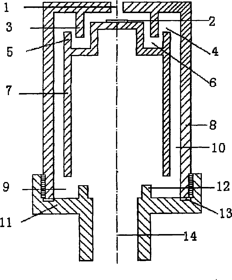
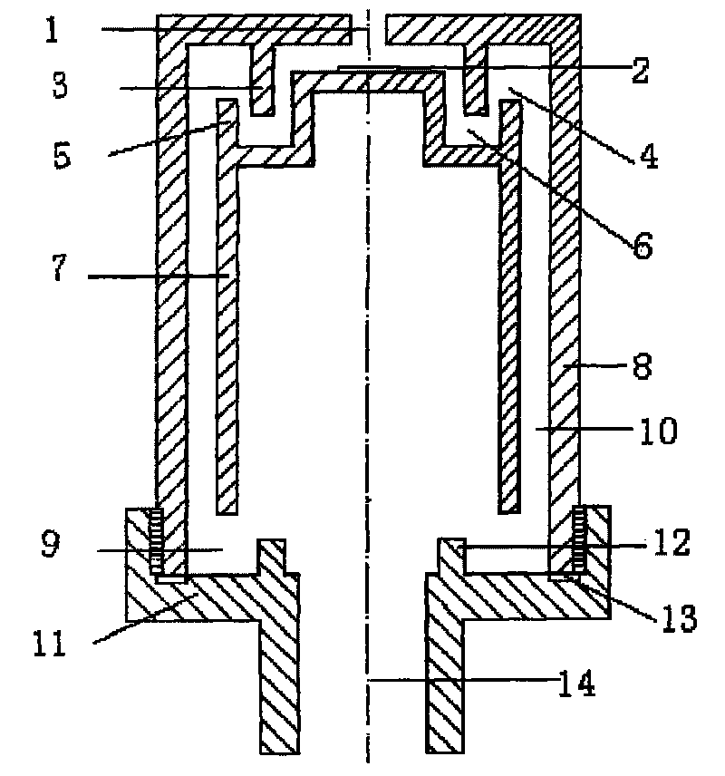
[0005] As shown in the figure, the non-leakage reversible automatic exhaust valve includes a valve cover (8) with a valve cover retaining ring (3) provided with an exhaust port (1), and a valve seat retaining ring (12) and a valve seat liquid tank (9 ) valve seat (11), the two are connected by threads to form the inner cavity (10) of the valve body, and a sealing ring (13) is arranged at the joint of the two bodies, and there is a buoy retaining ring (5) and a buoy liquid tank (6) in the valve The top is provided with the buoy (5) of the gasket (2), and the valve seat (11) is provided with an air inlet (14). Between the inner cavity (10) of the cover and the exhaust port (1), when the air discharge liquid level reaches the bottom of the buoy (7), a liquid seal is formed at the bottom of the buoy (7) to generate buoyancy and rise accordingly, and the buoy (7) The top gasket (2) closes the exhaust port (1). When the pressure increases and the gasket (2) cannot seal the exhaust p...


PUM


Abstract

The invention provides a non-leakage reversible automatic exhaust valve invented by utilizing atmospheric pressure principle. The non-leakage reversible automatic exhaust valve comprises a valve seat and a valve cover which are hermetically connected together to form a valve body; the valve body is internally provided with a convex floating cylinder which is opened wide at the lower part and is provided with a check ring liquid tank; a sealing gasket is arranged on the top of the floating cylinder opposite to the exhaust port; a check ring is arranged on the edge of the top outside the floating cylinder to form a floating cylinder liquid groove. When the liquid level of air discharge rises, a liquid sealing is formed at the bottom of the floating cylinder, the floating cylinder rises therewith relying on buoyancy and the exhaust port at the top of the valve cover is closed; when the pressure is increased and the liquid level exceeds the check ring of the floating cylinder, the feed liquor in the floating cylinder liquid groove form a liquid sealing, the valve cover air chamber forms barometric pressure, ensuring that the liquid level can not rise and achieves the purpose of no leakage; and when the liquid level drops to the position that no buoyancy is formed to the floating cylinder, the exhaust port is opened, and when the liquid level drops below the check ring of the valve seat, the bottom of the floating cylinder drops to the bottom of the valve seat liquid groove. A liquid sealing is formed by utilizing the residue liquid of the valve seat liquid groove and the valve seat check ring, and the barometric pressure principle is utilized to ensure that the air outside the floating cylinder can not enter to form inversion.

Description

technical field [0001] The invention relates to a new non-leakage reversible stop automatic exhaust valve designed using the principle of atmospheric pressure. Background technique [0002] Most of the exhaust valves currently used are based on the principle of lever, buoyancy, elastic force, bending, etc. to block the exhaust hole (port) and the air intake hole (port), which cannot solve the problem of liquid leakage under high pressure. And most of them are both exhaust and air intake, so that the system is emptied, which causes waste for the next operation. In addition, the existing exhaust valve has a complicated structure, poor sealing effect, and stability, reliability, and service life cannot be guaranteed. Problems existing in the prior art It is very necessary to develop a non-leakage reverse checkable exhaust valve. Contents of the invention [0003] In view of the problems existing in the above-mentioned prior art, the purpose of the present invention is to pro...

Claims


Application Information

Patent Timeline
IPC IPC(8): F16K1/00F16K31/18F16K27/02
Inventor 李树槐
Owner 李树槐
Learn More