
Traction electromagnet capable of precisely controlling displacement quantity

A traction electromagnet and precise control technology, applied in the traction field, can solve the problems of unstable running speed of objects, large dispersion of final positioning positions, and difficulty of electromagnets to meet positioning requirements, so as to suppress power supply fluctuations, avoid excessive impact, The effect of precise positioning

Active Publication Date: 2010-06-02
CANGZHOU SPIRAL STEEL TUBES
View PDF0 Cites 4 Cited by
  • Summary
  • Abstract
  • Description
  • Claims
  • Application Information

AI Technical Summary

Problems solved by technology

Due to the existence of the above problems, when the traditional electromagnet is used to drag the object, the running speed of the object is unstable, resulting in a large dispersion of the final positioning position. In the case where the stopper cannot be used for positioning, it is difficult for the existing electromagnet to meet the positioning requirements.

Method used


Image

  • Traction electromagnet capable of precisely controlling displacement quantity
  • Traction electromagnet capable of precisely controlling displacement quantity
  • Traction electromagnet capable of precisely controlling displacement quantity

Examples


Embodiment Construction

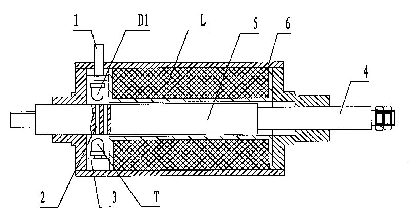
[0015] see figure 1 , the electromagnet of this device is made up of coil L, armature 5 and shell 6, and coil L generates magnetic field when electrified, and magnetic field line pulls armature 5 to do work, and armature 5 pulls object to do linear motion. The photoelectric sensor of the control circuit is fixedly connected with the casing 6 of the electromagnet through the circuit board 3 , and its luminescent tube D1 and photoelectric tube T are respectively located on both sides of the armature 5 of the electromagnet. A detection hole 2 is opened every 2mm along the axial direction on the armature. When the armature moves, the light emitted by the light-emitting tube D1 passes through each detection hole to reach the photoelectric tube in turn, and the photoelectric tube T outputs an electric pulse signal reflecting the moving speed of the armature.

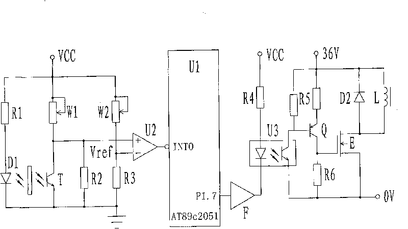
[0016] see figure 2 , The photoelectric sensor is composed of resistors R1, R2, light emitting tube D1, potentiometer W1 a...


PUM


Abstract

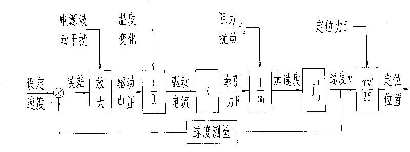
The invention relates to a traction electromagnet capable of precisely controlling displacement quantity, which is used for solving the problem of positioning an object in traction. The technical scheme is as follows: the electromagnet and a control circuit thereof constitute a closed loop control system, wherein the control circuit consists of a signal acquisition circuit, a single-chip microcomputer and a driving circuit, the signal acquisition circuit consists of a photoelectric sensor and a comparator, a light emitting tube and a photoelectric tube of the photoelectric sensor are respectively positioned on two sides of an armature of the electromagnet, two input ends of the comparator are respectively connected with an output signal and reference voltage of the photoelectric sensor, and an output end is connected with an INTO end of the single-chip microcomputer; the input end of the driving circuit is connected with a P1.7 end of the single-chip microcomputer, the output end drives a coil of the electromagnet; and a plurality of equidistant inspection holes are formed on the armature of the electromagnet along the direction of an axial line. The device takes motion parameters as closed loop control objects, thereby leading the object in the traction to acquire precise motion velocity and further implementing the precise positioning of the object in the traction.

Description

technical field [0001] The invention relates to a traction electromagnet capable of precisely positioning a towed object, and belongs to the technical field of traction. Background technique [0002] Electromagnet is a commonly used traction device. In many cases, people need to control the speed and final position of the towed object. Existing traction electromagnets generally indirectly control the speed and final position of the pulled object by controlling the voltage applied to both ends of its coil, and the movement speed of the armature is controlled in an open-loop manner. However, in practical applications, it is often necessary to precisely control its operating speed to avoid excessive impact; the power supply voltage often fluctuates, causing the voltage on the coil to be unstable, and the traction force generated by the electromagnet varies with the voltage, affecting the stability of the speed; When the coil temperature rises, the coil resistance increases, ev...

Claims


Application Information

Patent Timeline
Patent Type & Authority Applications(China)
IPC IPC(8): H01F7/18
Inventor 张弛魏泽鼎
Owner CANGZHOU SPIRAL STEEL TUBES
Learn More