Remote control lamp

A lamp and lamp body technology, applied in discharge lamps, incandescent lamps, electric lamp circuit layout and other directions, can solve the problems of waste, increase the workload of installation, scrapped electronic circuit boards, etc., to save money, facilitate maintenance and replacement, save money The effect of installation work

Inactive Publication Date: 2010-06-02
SHANGHAI SECOND POLYTECHNIC UNIVERSITY
View PDF10 Cites 5 Cited by
  • Summary
  • Abstract
  • Description
  • Claims
  • Application Information

AI Technical Summary

Problems solved by technology

If the electronic circuit board is installed in the screw lamp body, once the lamp body is scrapped, the electronic circuit board must also be scrapped. For example, the screw incandescent lamp itself is cheap, but its service life is also very short. Once the lamp body is scrapped, The electronic circuit board whose price is several times higher than it will also be scrapped, causing a lot of waste
If the electronic circuit board is installed in the screw lamp hold

Method used


Image

  • Remote control lamp
  • Remote control lamp
  • Remote control lamp

Examples


Embodiment 1

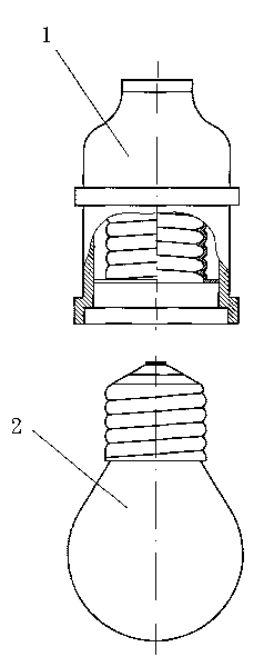
[0067] combine figure 1 and figure 2 Be explained.

[0068] figure 1 is a schematic diagram of a lamp in the prior art; figure 2 It is a schematic diagram of the remote control lamp of the present invention. Explanation of the symbols in the figure: 1. Hanging screw lamp holder; 2. Screw incandescent lamp; 3. Bridge connector.

[0069] In this embodiment, the inventive remote control lamp such as figure 2 As shown, it consists of three parts, which are the hanging screw lamp holder marked 1, the screw incandescent lamp marked 2, and the bridge connector marked 3. Wherein the hanging screw socket 1 and the screw incandescent lamp are traditional prior art lamps, and the bridge connector is unique to the present invention.

[0070] for figure 1 The prior art lamps shown in use can be conveniently transformed into remote control lamps by using the technology of the present invention: as long as the screw-mounted incandescent lamp 2 is unscrewed, the bridge connector 3 i...

Embodiment 2

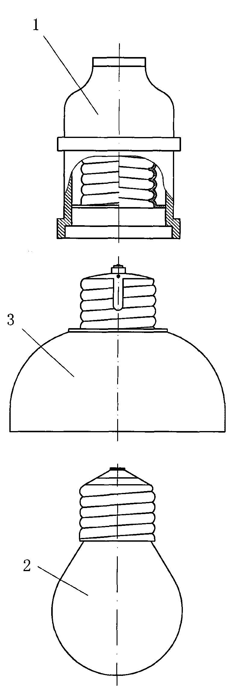
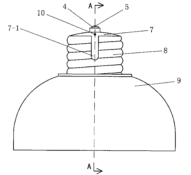
[0074] combine Figure 2 to Figure 6 A total of 5 pictures are used for illustration. figure 2 It is a schematic diagram of the remote control lamp of the present invention; image 3 It is the front view of the bridge connector in the present invention; Figure 4 Yes image 3 top view of Figure 5 Yes image 3 left view of Image 6 Yes image 3 A-A to the sectional view.

[0075] The remote control lamp of the present invention comprises: a screw socket, a screw lamp body, a bridge connector 3, and a remote controller. The first three are as follows: figure 2 shown.

[0076] The base of the bridge connector 3 includes a bell-shaped housing 9 with a circular lower cover 29 with a large hole in the center; the housing 9 is provided with a hole 9-1 for optical signals to pass through.

[0077] The bridge connector 3 is provided with a second external thread structural part facing upwards, which is threadedly matched with the first internal thread structural part on the...

Embodiment 3

[0084] In the above-mentioned embodiment two, and in Image 6 Among them, the externally threaded structural part (8) in the second externally threaded structural part is manufactured as one with the shell 9 and is made of plastic.

[0085] In this embodiment, the externally threaded structural part (8) and the housing 9 are manufactured separately. Wherein, the externally threaded structural parts (8) with external threads are made of metal, and the method can be imitated figure 1 The metal head of the incandescent lamp 2 with the middle screw socket; the shell 9 is made of high temperature resistant plastic.

[0086] There are two ways to connect the shell 9 and the external threaded structural part (8): the first method is to fix the two parts to each other after they are manufactured, and the connection method is such as bonding with an adhesive; the second method is First manufacture the metal external thread structural part (8), then put this part into the plastic mold...


PUM


Abstract

The invention relates to the technical field of lighting lamps and discloses a remote control lamp in order to solve the problem of too many scrapped electronic circuit boards or difficult installation of the traditional remote control lamp. The remote control lamp comprises an edison base, and the like, and is characterized by comprising a gap connector (3), wherein a second external threaded component is arranged in the upward direction of the gap connector, and a second internal threaded component is arranged in the downward direction of the gap connector; an electronic circuit board is arranged in a base body; and the second external threaded component and the second internal threaded component are electrically connected through leads and the electronic circuit board. The remote control lamp has the advantages that the structure is novel; the lamp body can be directly screwed in the gap connector after the gap connector is directly screwed in the base, thereby achieving very convenient use, maintenance and replacement; the base does not need replacement, thereby saving installation; only the broken lamp body needs to be replaced and the electronic circuit board can be used continually, thereby saving money.

Description

technical field [0001] The invention relates to the technical field of lighting fixtures, in particular to a remote control lighting fixture. Background technique [0002] In the prior art, there is a type of lamp that uses a remote controller to control lighting fixtures to be turned on or off; an electronic circuit board containing a photoelectric receiving tube is installed in the lamp, and the user sends an optical signal (such as an infrared ray) to the photoelectric receiving tube through the remote controller. Signal) or electromagnetic wave signal (such as radio signal), after the photoelectric receiving tube receives the signal, it is amplified and pushed by the electronic circuit board, so that the connecting line is connected or cut off, so that the lighting fixture is lit or extinguished. [0003] In the prior art, non-remote-controlled ordinary lighting fixtures are usually connected by screw structure; for example, if lighting fixtures are installed on the indo...

Claims


Application Information

Patent Timeline
IPC IPC(8): H01R33/22H01R33/94H01R33/955F21V23/06H05B37/02
Inventor 靳炜张永红
Owner SHANGHAI SECOND POLYTECHNIC UNIVERSITY
Why Eureka
Try Eureka