Brake control system and brake control method

一种制动控制、控制阀的技术,应用在电力制动系统、制动器、驱动互动等方向,能够解决影响制动控制性能等问题

Inactive Publication Date: 2010-06-02
TOYOTA JIDOSHA KK
View PDF2 Cites 10 Cited by
  • Summary
  • Abstract
  • Description
  • Claims
  • Application Information

AI Technical Summary

Problems solved by technology

This can adversely affect brake control performance

Method used


Image

  • Brake control system and brake control method
  • Brake control system and brake control method
  • Brake control system and brake control method

Examples


Embodiment Construction

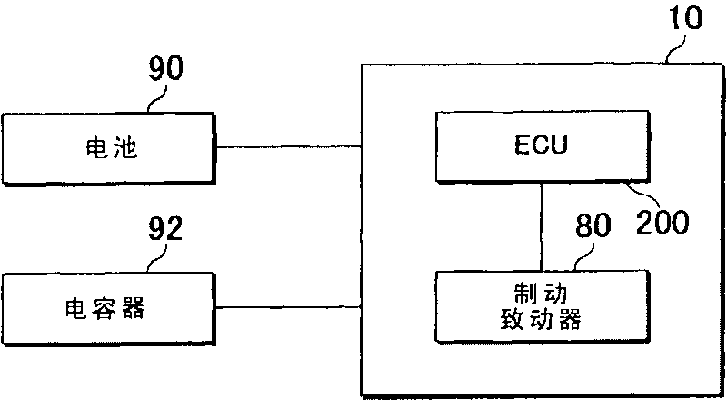
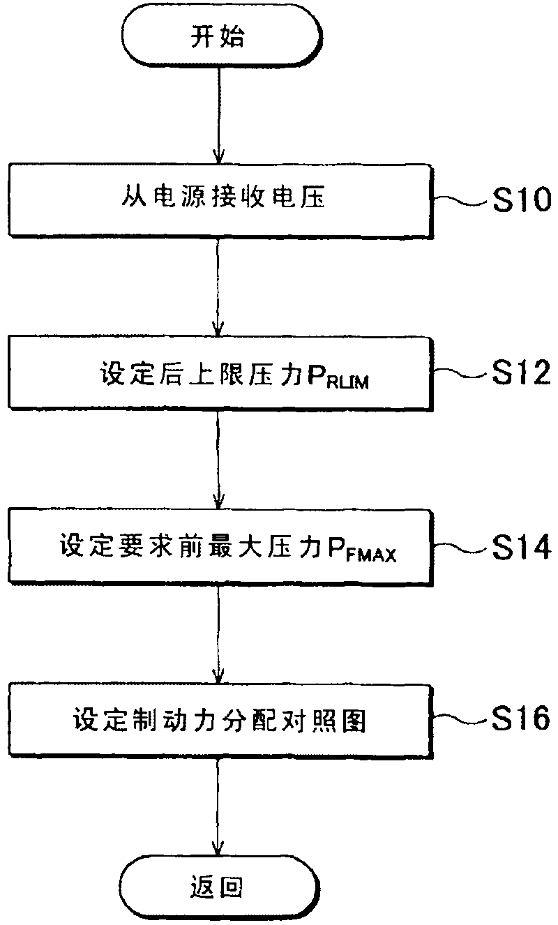
[0045] First, concepts of exemplary embodiments of the present invention will be described. In these example embodiments, the control portion performs braking force distribution control corresponding to the state of charge (SOC) of the power source. This control optimally regulates the distribution of braking force between the wheels based on the state of charge of the power supply in the brake control system. For example, the braking force distribution between the front wheels and the rear wheels is set such that a target braking force or a maximum braking force is generated in accordance with a voltage that can be supplied from a battery to the brake control system. Such control may also be referred to simply as "optimized distribution control" hereinafter.

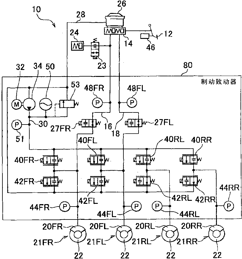
[0046] In this optimal distribution control, the control section sets an upper limit pressure in at least one wheel cylinder. Then, during braking, the control section controls the target pressure of the wheel cylinde...


PUM


Abstract

A brake control system (10) includes a first wheel cylinder (20RL, 20RR) that applies braking force to a first wheel according to hydraulic pressure; a second wheel cylinder (20FL, 20FR) that applies braking force to a second wheel according to hydraulic pressure; a brake actuator (80) that receives current and individually controls the hydraulic pressure of the first wheel cylinder and the hydraulic pressure of the second wheel cylinder; a power supply (90, 92) that supplies the current to the brake actuator (80); and a control portion (200) which sets a braking force distribution between the first wheel and the second wheel based on the state-of-charge of the power supply, and controls the brake actuator (80) according to the braking force distribution.

Description

technical field [0001] The present invention relates to a brake control system and a brake control method that control braking force applied to wheels of a vehicle. Background technique [0002] Japanese Patent Application Publication No. 2001-171498 (JP-A-2001-171498) describes a brake control system that sets a target pressure based on the amount of operation of the brake pedal by the driver and controls a solenoid valve to achieve target pressure. Furthermore, Japanese Patent Application Publication No. 10-271607 (JP-A-10-271607) describes a braking control system for an electric vehicle provided with a mechanical braking device and regenerative braking using an electric motor device. This brake control system determines the split ratio between regenerative braking and mechanical braking based on the state of charge (SOC) of the battery. [0003] A brake control system in the background art is designed to control a braking force on the premise that sufficient electric ...

Claims


Application Information

Patent Timeline
Patent Type & Authority Applications(China)
IPC IPC(8): B60T8/1766
CPCB60L7/12B60L11/005B60T8/267B60T8/88B60T8/1766B60L3/0038B60T8/4081B60L7/26B60L11/14B60T8/266B60L11/1861B60L2250/10B60L2240/547B60L50/16B60L50/40B60L58/12Y02T10/70Y02T10/7072
Inventor 宫崎彻也山本贵之
Owner TOYOTA JIDOSHA KK
Why Eureka
Try Eureka