Beam transport system and method for linear accelerators

A linear accelerator and beam tube technology, applied in the direction of linear accelerators, accelerators, electrical components, etc.

Active Publication Date: 2010-06-02
LAWRENCE LIVERMORE NAT SECURITY LLC
View PDF12 Cites 12 Cited by
  • Summary
  • Abstract
  • Description
  • Claims
  • Application Information

AI Technical Summary

Problems solved by technology

Also, while singlets have been used for lateral focusing as known in the art, singlets have not been used for longitudinal beam compression

Method used


Image

  • Beam transport system and method for linear accelerators
  • Beam transport system and method for linear accelerators
  • Beam transport system and method for linear accelerators

Examples


Embodiment Construction

[0056] A. Compact accelerator with ribbon-like Blumlein

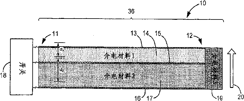
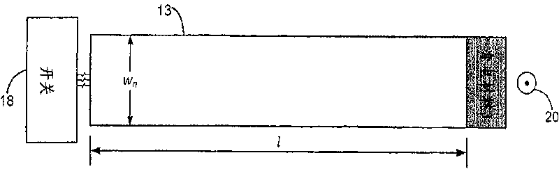
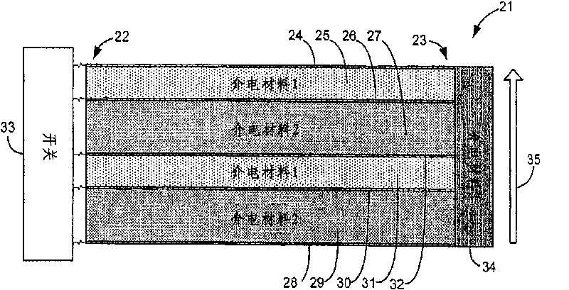
[0057] Turn to the attached picture below, Figure 1 to Figure 12 denotes a compact linac used in the invention having at least one ribbon-shaped Blumlein module directing a propagating wavefront between a first end and a second end and controlling the output pulse at the second end. Each Blumlein module has first, second and third planar conductor strips, the first dielectric strip is between the first conductor strip and the second conductor strip, and the second dielectric strip is between the second conductor strip and the third conductor strip between. Furthermore, the compact linear accelerator includes a high voltage power supply connected to charge the second conductor strip to a high potential, and a switch for switching the high potential in the second conductor strip to at least one of the first conductor strip and the third conductor strip. switch to initiate propagating wavefronts of opposite polarity i...


PUM


Abstract

A charged particle beam transport system and method for linear accelerators includes a lens stack having two electrodes serially arranged along an acceleration axis between a charged particle source, and a linear accelerator. After producing and extracting a bunch of charged particles (i.e. particle beam) from the particle source, a voltage difference between the two electrodes is ramped in time to longitudinally compress the particle beam to be shorter than the pulsewidth of acceleration pulses produced in the accelerator. Additional electrodes may be provided in the lens stack for performing transverse focusing of the charged particle bunch and controlling a final beam spot size independent of the current and energy of the particle beam. In a traveling wave accelerator embodiment having a plurality of independently switchable pulse-forming lines, beam transport can also be controlled by triggering multiple adjacent lines simultaneously so that the physical size of the accelerating electric field is longer than the charged particle bunch, as well as by controlling trigger timing of the pulse-forming lines to perform alternating phase focusing.

Description

[0001] Cross References to Related Documents [0002] This application claims priority to US Provisional Application No. 60 / 934,213, filed June 11,2007. This application is also a continuation-in-part of earlier application serial number 11 / 586,378, filed October 24, 2006, which is a continuation-in-part of earlier application serial number 11 / 036,431, filed January 14, 2005 , earlier application 11 / 036,431 claimed priority to U.S. Provisional Application 60 / 536,943, filed January 15, 2004; and application 11 / 586,378 also claimed U.S. Provisional Application 60, filed October 24, 2005 / 730,128, 60 / 730,129 and 60 / 730,161 and the priority of U.S. Provisional Application No. 60 / 798,016, filed May 4, 2006, the entire contents of which are hereby incorporated by reference. [0003] Federally Sponsored Research or Development [0004] Pursuant to Agreement DE-AC52 between the U.S. Department of Energy and Lawrence Livermore National Security, LLC for the Operation of Lawrence Liverm...

Claims


Application Information

Patent Timeline
Patent Type & Authority Applications(China)
IPC IPC(8): H05H9/00
CPCH05H9/00H05H7/02
Inventor 陈瑜娟乔治·J·卡波拉索斯科特·纳尔逊
Owner LAWRENCE LIVERMORE NAT SECURITY LLC
Why Eureka
Try Eureka