
Self-potential roller-type cross wedge rolling mill

A cross-wedge rolling mill and roll-type technology, which is applied in the field of plastic forming equipment, can solve problems such as low bearing life, uneven force on the rolled piece, and large elastic deformation of the roll system, so as to improve precision and product quality, and ensure design The effect of life and bearing load uniformity

Inactive Publication Date: 2012-01-25
NINGBO UNIV
View PDF0 Cites 6 Cited by
  • Summary
  • Abstract
  • Description
  • Claims
  • Application Information

AI Technical Summary

Problems solved by technology

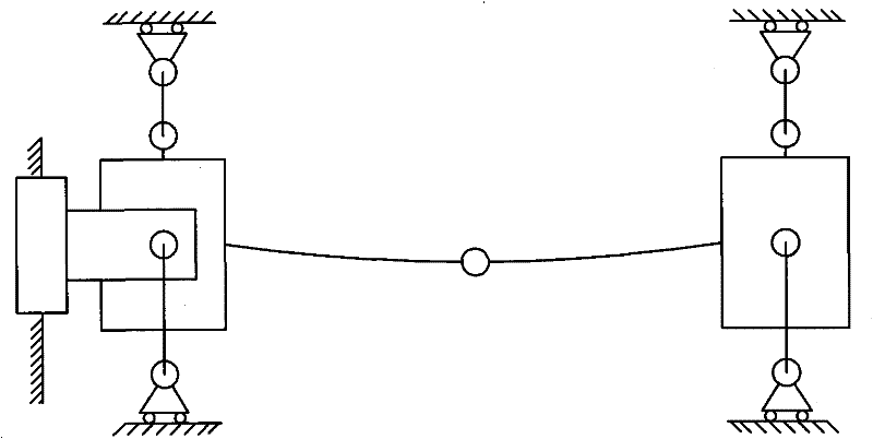
However, due to the long roll body required for rolling long shaft parts such as automobile half shafts, the elastic deformation of the roll system of the cross wedge rolling mill is relatively large during the rolling process, resulting in unbalanced loads on the bearings of the rolling mill, and the bearing life is much lower than the design life. , and it will also lead to uneven stress on the rolled piece during the rolling process, resulting in uneven internal structure and deformation of the rolled piece, resulting in defects such as looseness of the rolled piece
Therefore, the current cross wedge rolling mills at home and abroad are difficult to meet the large-scale production of long shaft parts or multiple shaft parts in one rolling.

Method used


Image

  • Self-potential roller-type cross wedge rolling mill
  • Self-potential roller-type cross wedge rolling mill
  • Self-potential roller-type cross wedge rolling mill

Examples


Embodiment Construction

[0024] The present invention will be further described in detail below in conjunction with the accompanying drawings and embodiments.

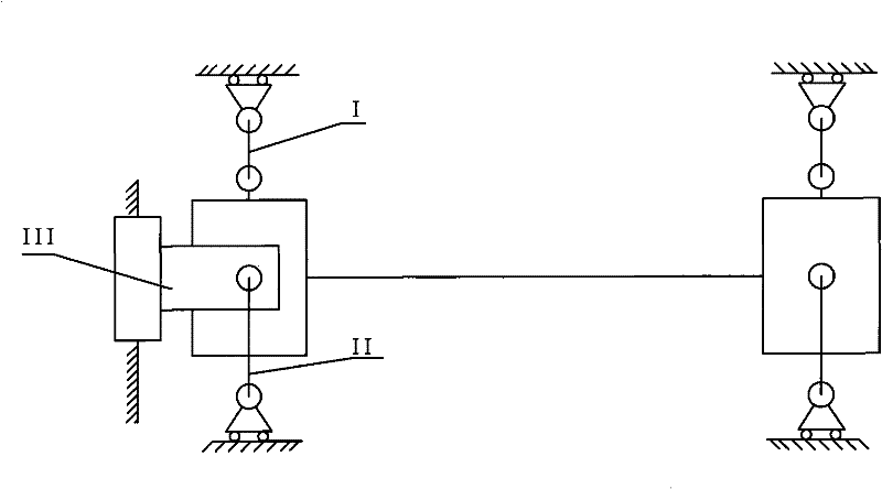
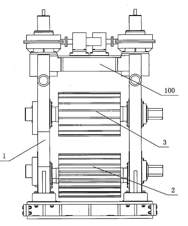
[0025] As shown in the figure, a self-positioning cross wedge rolling mill includes a frame 1, an upper roll 3, a lower roll 2 and a driving device for driving the upper roll 3 to move up and down. The bearing housing 31, the lower bearing housing 5 is provided at both ends of the lower roll 2, and the first self-positioning adjustment device is provided between the lower end of the lower bearing housing 5 and the frame 1, and the first self-positioning adjustment device includes a first connecting screw 11 And the upper convex arc surface block 12, the double concave arc surface block 13 and the lower convex arc surface block 14 that are stacked successively from bottom to top, the arc surfaces of the upper convex arc surface block 12 and the lower convex arc surface block 14 are respectively connected with the double concave arc surface The ...


PUM


Abstract

The invention discloses a self-potential roll-type cross wedge rolling mill, comprising a rack, an upper roll, a lower roll and a driving device used for driving the upper roll to move up and down. Upper bearing blocks are arranged at the two ends of the upper roll and lower bearing blocks are arranged at the two ends of the lower roll. Prestressed supports are fixedly arranged at the upper ends of the lower bearing blocks. Adjusting levers are connected on the prestressed supports by bolts. The cross wedge rolling mill is characterized in that a first self-potential adjusting device is arranged between the lower ends of the lower bearing blocks and the rack; a second self-potential adjusting device is arranged between the adjusting levers and the lower end faces of the upper bearing blocks; a third self-potential adjusting device is arranged between the upper end faces of the upper bearing blocks and the driving device; and axial self-potential adjusting devices with the same structure are arranged between the sides, positioned at the operating sides, of the upper bearing blocks and the rack as well as between the sides, positioned at the operating sides, of the lower bearing blocks and the rack. The invention has the following advantages: the bearing load is uniform when the rolling mill works, the design life of the bearing is ensured, the inner organizations of the rolled pieces are uniform, the rolling precision and the product quality are improved and scale production of the shaft parts by cross wedge rolling is realized.

Description

technical field [0001] The invention relates to a plastic forming equipment for shaft parts, in particular to a self-positioning cross wedge rolling mill. Background technique [0002] Cross wedge rolling is a new forming process of shaft parts, which has the advantages of high efficiency and material saving, and has been widely used at home and abroad. With the continuous development of cross wedge rolling technology, the range of rolled products is also increasing. For example, the cross wedge rolling and multi-wedge synchronous technology can be used to roll automobile half shafts and railway vehicle axles. However, due to the long roll body required for rolling long shaft parts such as automobile half shafts, the elastic deformation of the roll system of the cross wedge rolling mill is relatively large during the rolling process, resulting in unbalanced loads on the bearings of the rolling mill, and the bearing life is much lower than the design life. , and it will also...

Claims


Application Information

Patent Timeline
Patent Type & Authority Patents(China)
IPC IPC(8): B21B1/00B21B31/16B21B35/00
Inventor 束学道李传斌
Owner NINGBO UNIV
Learn More