Guide structure for upper cutter of bag making machine

A guiding structure, bag making machine technology, applied in the direction of container manufacturing machinery, box making operations, rigid/semi-rigid container manufacturing, etc., can solve the problems of complicated installation process of cutter, difficult adjustment of cutter position, complex structure, etc. Achieve the effect of compact structure, simple structure and prolonging service life

Active Publication Date: 2015-01-28
广东和胜机械实业有限公司
View PDF4 Cites 0 Cited by
  • Summary
  • Abstract
  • Description
  • Claims
  • Application Information

AI Technical Summary

Problems solved by technology

The structure of the existing cutting device is complex, the position of the cutter is not easy to adjust, and the installation process of the cutter is complicated, time-consuming and laborious

Method used


Image

  • Guide structure for upper cutter of bag making machine
  • Guide structure for upper cutter of bag making machine
  • Guide structure for upper cutter of bag making machine

Examples


Embodiment Construction

[0016] The specific implementation manner of the present invention will be described below in conjunction with the accompanying drawings.

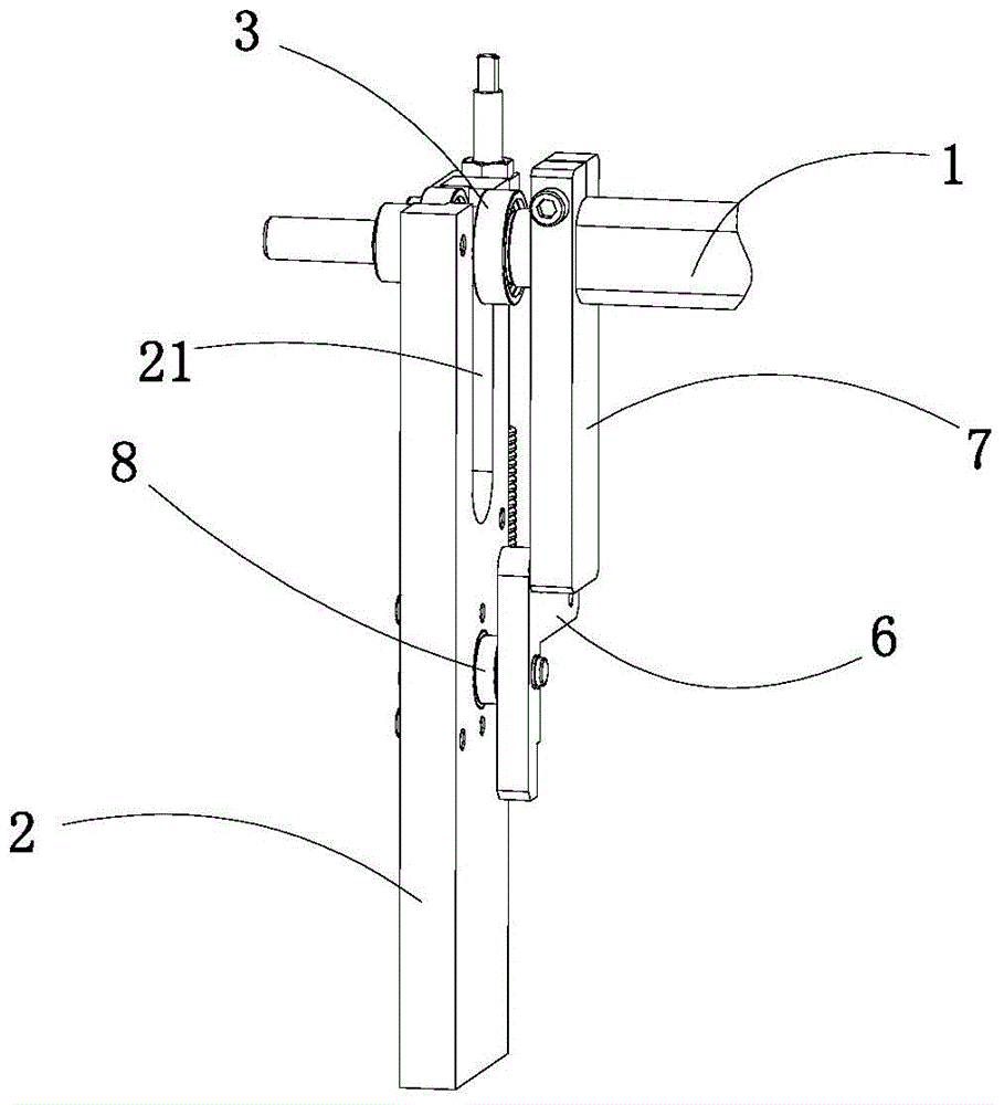
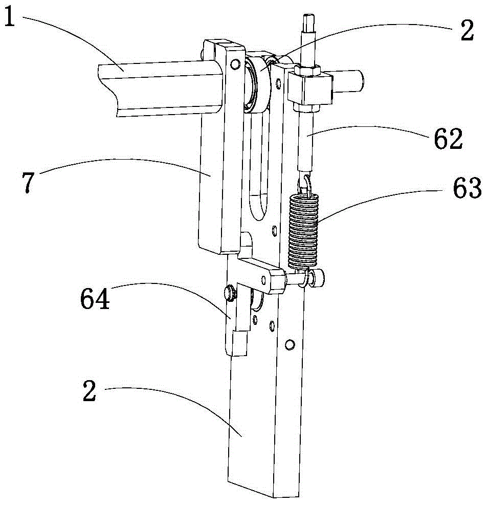
[0017] like Figure 1 to Figure 5 As shown, the guiding structure of the cutting knife on the bag making machine of this embodiment includes a lifting cross bar 1 for the upper cutting knife on the device, the end sliding device of the lifting cross bar 1 is on the frame plate 2, and the lifting cross bar 1 The end is slided in the U-shaped groove 21 on the upper end of the frame plate 2 by means of the bearing 3;

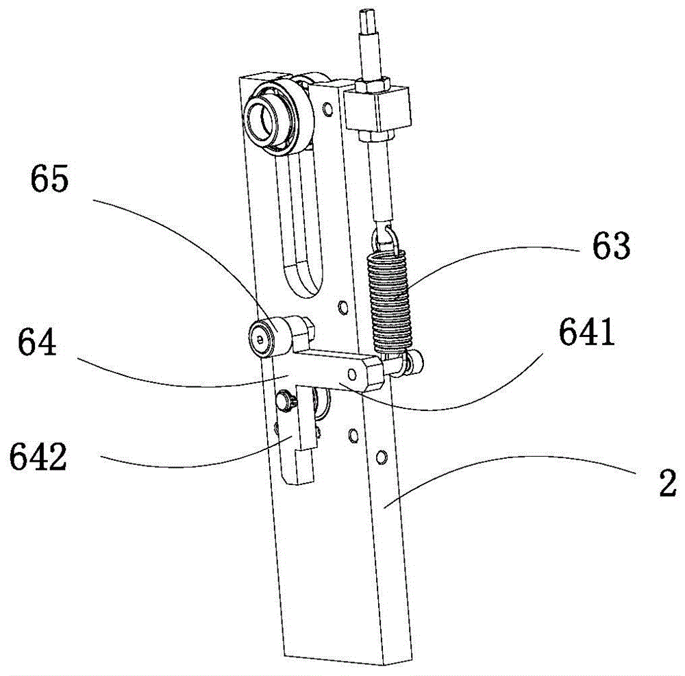
[0018] The device on the frame plate 2 has an elastic guide structure 6, which is slidingly connected with the sliding sleeve 7 installed on the frame plate 2, and the upper end of the sliding sleeve 7 is fixedly connected with the elevating cross bar 1, and its side has a chute 71 The elastic guide structure 6 includes a guide frame 64 hinged on the inside of the frame plate 2. The guide frame 64 is a T-shaped structure, incl...


PUM


Abstract

The invention relates to a guide structure for an upper cutter of a bag making machine. The guide structure comprises a lifting cross rod for arranging the upper cutter, wherein the end part of the lifting cross rod is arranged in a U-shaped groove in the upper end of a rack plate through a bearing in a sliding way; an elastic guide structure is arranged on the rack plate, and is in sliding connection with a sliding sleeve on the rack plate; the upper end of the sliding sleeve is fixedly connected with the lifting cross rod, and a sliding chute is formed in the lateral surface of the sliding sleeve; the elastic guide structure comprises a guide frame hinged to the inner side of the rack plate; the guide frame is of a T-shaped structure, and comprises a guide side plate and a cross plate which are fixedly connected with each other; the guide side plate is arranged on the rack plate in a rotating way; a first roller arranged in the sliding chute of the sliding sleeve is arranged at the upper end of the guide side plate; the end part of the cross plate is elastically connected with the rack plate through a spring vertically arranged on the lateral surface of the rack plate. The guide structure is simple, reasonable in design and compact; the elastic guide structure is used for realizing swinging guide, so that abrasion caused by hard sliding to the structure is avoided, the service life is prolonged, and a self adjustment function is realized.

Description

technical field [0001] The invention relates to the technical field of mechanical equipment, in particular to a bag making machine. Background technique [0002] The bag making machine is a special equipment for making packaging bags, which is widely used in the production of packaging bags made of various plastics, paper and other materials. The process of forming a packaging bag by a high-speed bag making machine is: guiding the upper film and the lower film to be transported separately, overlapping the upper and lower films at a suitable position, and the overlapped films are heat-sealed longitudinally and transversely to form an integrated structure of multiple small bags, and finally separated. Cut into multiple pouches. Among them, the slitting process generally includes two processes of front cross cutting and rear slitting. The rear slitting is the process of separating the small bags arranged in front and rear from the film, and is completed by the rear slitting me...

Claims


Application Information

Patent Timeline
Patent Type & Authority Applications(China)
IPC IPC(8): B31B1/20B31B50/20
Inventor 孙毅刚
Owner 广东和胜机械实业有限公司
Why Eureka
Try Eureka