Eureka AIR delivers breakthrough ideas for toughest innovation challenges, trusted by R&D personnel around the world.

Processing die of brush body of pressurized water-saving cleaning brush

A technology for processing molds and brush bodies, which is applied in the field of processing molds for cleaning brush bodies, can solve the problems of affecting product quality, high labor intensity, troublesome operation, etc., and achieve the effects of improving pass rate, reducing labor intensity, and improving work efficiency

Inactive Publication Date: 2010-06-09
任正志 +1
View PDF0 Cites 3 Cited by
  • Summary
  • Abstract
  • Description
  • Claims
  • Application Information

AI Technical Summary

Problems solved by technology

However, the structure of the stud, the water outlet and the water inlet are intertwined, and there are certain difficulties in manufacture. In addition, the interface of the spray gun connected with the handle is generally external thread, so the interface of the handle needs to be made of internal thread, and the internal thread It is difficult to demould threaded joints. In the existing technology, manual demoulding is generally used for the thread (whether it is internal thread or external thread), that is, the product is taken out together with the insert used to form the thread (that is, it is separated from the core) , and then rotate the product out of the insert, and finally install the insert back into the core. Therefore, manual demoulding is not only cumbersome to operate, but also low in efficiency and labor-intensive, and will affect the quality of the product

Method used


Image

  • Processing die of brush body of pressurized water-saving cleaning brush
  • Processing die of brush body of pressurized water-saving cleaning brush
  • Processing die of brush body of pressurized water-saving cleaning brush

Examples


Embodiment Construction

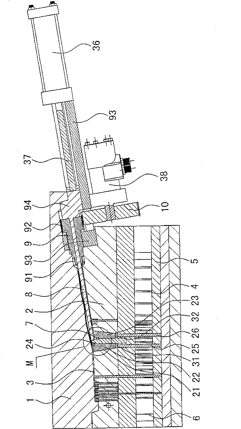
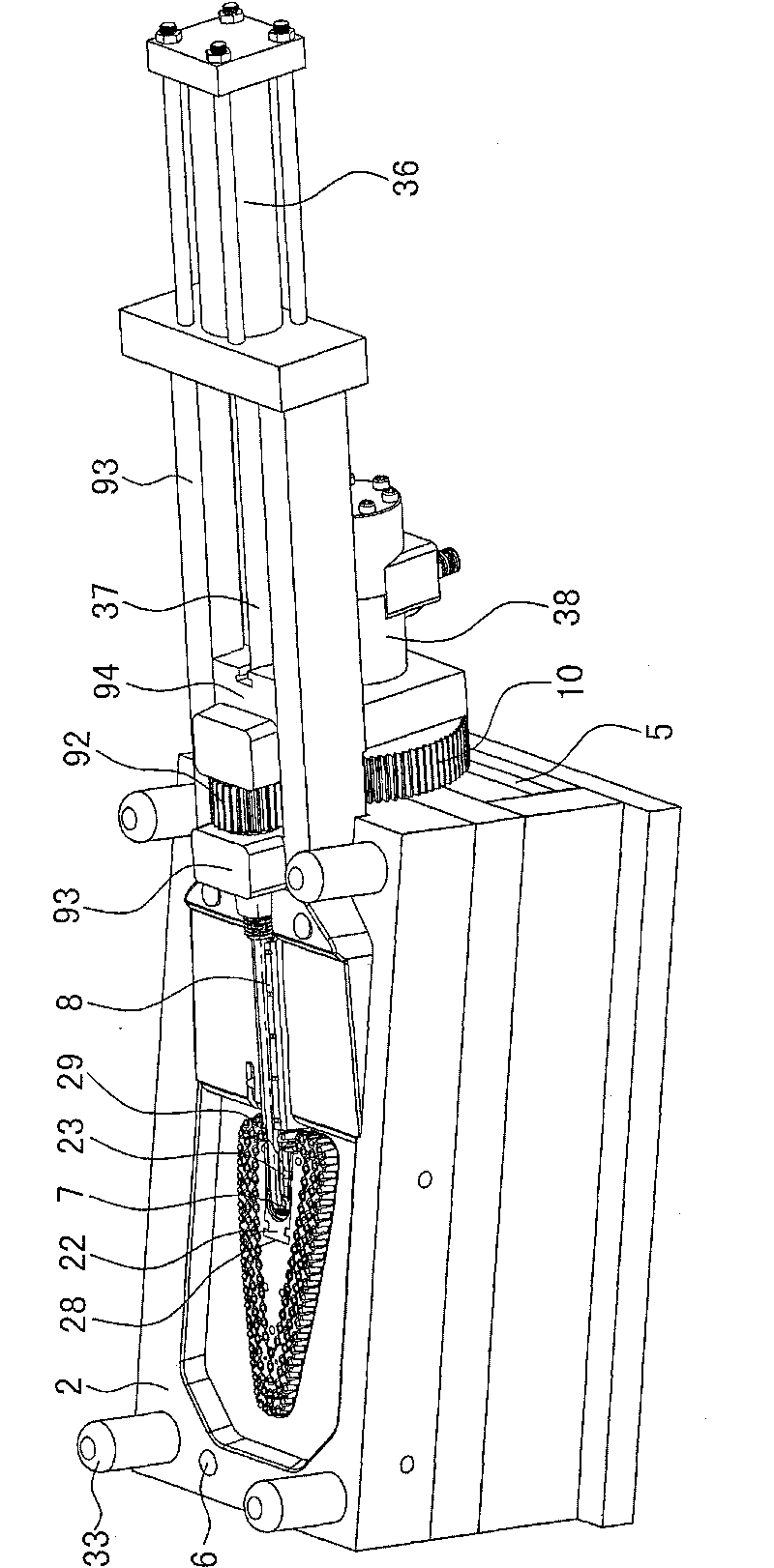
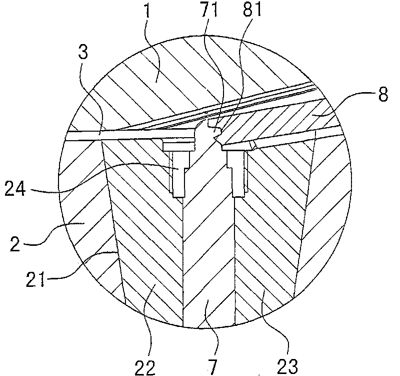
[0013] The invention discloses a processing mold for a pressurized water-saving cleaning brush body, such as Figure 6 As shown, the brush body 12 of the pressurized water-saving cleaning brush is made into one with the handle 11, and the middle part of the brush body 12 is shaped on a longitudinal water outlet hole 15, and the longitudinal water outlet hole 15 communicates with the horizontal water inlet hole 14 of the handle, and the longitudinal water outlet hole 15 The mouth of the hollow stud 16 is shaped on, and the mouth of the hollow stud 16 installs the nozzle 19 through the nut 18, and the brush body bottom surface installs the bristles 13, as Figure 1-Figure 5As shown, the processing mold of the brush body includes a cavity 1 installed on the movable template and a core 2 installed on the fixed template. The cavity 1 and the core 2 constitute the cavity 3 of the brush body. The cavity 1 and the core 2. Positioned by the guide post 33, the mold cavity is driven by t...


PUM


Abstract

The invention relates to a processing die of a brush body of a pressurized water-saving cleaning brush. The brush body and a handle are made into a whole; a water outlet hole is formed in the brush body; the water outlet hole is communicated with a water inlet hole of the handle; a stud is arranged at the opening part of the water outlet hole; a nozzle is installed at the opening part of the stud through a nut; brush bristles are installed on the bottom surface of the brush body; the processing die comprises a mold cavity and a mold core; the mold cavity and the mold core form a die cavity of the brush body; the mold cavity is driven by a die opening and closing mechanism; a thimble hole and a resetting rod hole for a thimble and a resetting rod to pass through are arranged on the mold core; the thimble and the resetting rod are fixed on a thimble fixing plate; and the thimble fixing plate is driven by an oil cylinder on an injection molding machine. The invention is characterized in that a water outlet core is arranged at the middle part of the mold core; the top of the water outlet core is connected with one end of a water inlet core; a threaded core is installed outside the water inlet core; external threads are arranged at one end of the threaded core; a driven gear is arranged at the other end of the threaded core; the driven gear is meshed with a driving gear; the driving gear is driven by a rotary oil cylinder; and the other end of the water inlet core is fixedly connected with a piston rod of a core oil cylinder.

Description

technical field [0001] The invention relates to a processing mold for cleaning a brush body, belonging to the field of mechanical manufacturing. Background technique [0002] Cars, highway guardrails, telephone booths, car sentry boxes, family kitchens, doors and windows, toilets, etc. need to be cleaned frequently after they are contaminated by sand and dust. Existing cleaning brush is made up of handle, brush body and bristle, and handle is connected high-pressure pump through water pipe, and handle is shaped on water inlet hole, and water inlet hole leads to brush body, and brush body has water outlet. When working, the high-pressure pump enters the atomized water from the water inlet of the handle into the brush body through the water pipe, and then sprays it directly through the water outlet hole of the brush body. Due to the large water outlet hole, the water consumption is large and the waste is serious; The cleaning effect is not ideal, so I applied for a related pa...

Claims


Application Information

Patent Timeline
Patent Type & Authority Applications(China)
IPC IPC(8): B29C45/26B29C45/33B29C45/40B29L1/00B29L31/42
Inventor 任正志戴余富
Owner 任正志
Why Eureka
Eureka Blog
Learn More