Detection platform for luminous component with a plurality of luminous elements and detection method thereof

A technology for light-emitting components and light-emitting elements, which is applied in photometry, optical radiation measurement, measurement devices, etc., can solve unsolved problems and achieve the effect of improving output rate

Inactive Publication Date: 2010-06-09
CHROMA ELECTRONICS SHENZHEN
View PDF0 Cites 5 Cited by
  • Summary
  • Abstract
  • Description
  • Claims
  • Application Information

AI Technical Summary

Problems solved by technology

[0006] However, the known technology only discusses the static sensing after positioning of the light source under test, and the object of each measurement and inspection is the entire light source under test, which does not solve the problem when there are many light-emitting elements in a group of light sources under test. , to find out which of the many light-emitting components is wrong; that is, once a problem with a certain light-emitting component is found, an additional step must be performed to confirm where the wrong light-emitting component is before further processing and correction

Method used


Image

  • Detection platform for luminous component with a plurality of luminous elements and detection method thereof
  • Detection platform for luminous component with a plurality of luminous elements and detection method thereof
  • Detection platform for luminous component with a plurality of luminous elements and detection method thereof

Examples


Embodiment Construction

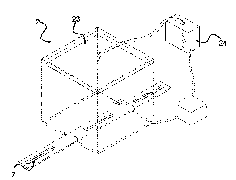
[0037] The technical content, characteristics and effects of the present invention will be clearly presented in the following detailed description of the preferred embodiments with accompanying drawings; The light-emitting elements are arranged along one length direction, and the bracket lines necessary for the base of the machine are omitted to avoid disorder of the drawing.

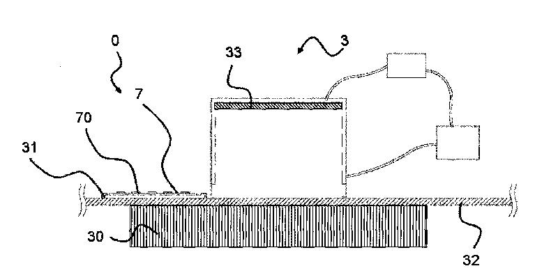
[0038] Such as image 3As shown, this is the first embodiment of the present invention. The light-emitting component testing machine 3 is used to measure the light-emitting state of the light-emitting component 7 with a plurality of light-emitting elements 70, and includes: a base 30, a set of bearings, The enabling device 31 for enabling the light-emitting component 7 , a set of sensing devices 33 capable of sensing a plurality of light-emitting elements 70 at the same time, and a group of moving devices 32 for driving the enabling device 31 to move.

[0039] Such as image 3 and Figure 4 As shown,...


PUM


Abstract

In the invention, a set of bearing and enabling device arranged on a base of a platform is utilized to bear and enable a luminous component to be detected; the bearing and enabling device and a sensing device are driven by a set of moving device to relatively move along the length direction of the corresponding enabled luminous component; and a set of sensing device is enabled to receive luminous state information of the luminous component in turn within a large range and transmits a sensing signal. Therefore, by referring to the known standard luminous state information and detecting the abnormality of elements of the luminous component, the simple, convenient and fast detection platform for the luminous component with a plurality of luminous elements and a detection method thereof are obtained.

Description

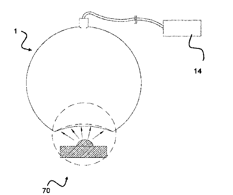
【Technical field】 [0001] The invention relates to a light-emitting component testing machine and a testing method thereof, in particular to a light-emitting component testing machine with a plurality of light-emitting elements and a testing method thereof. 【Background technique】 [0002] Such as figure 1 As shown, the integrating sphere 1 is a hollow spherical cavity, and the inner wall of the spherical cavity is generally coated with reflective properties. When the integrating sphere 1 is used in practice, the light beam emitted by the light-emitting element 70 to be tested is input into the hole from the bottom of the integrating sphere 1. Injected, after the complex reflection and diffusion of the inner wall of the spherical cavity, the light energy absorbed by the cavity wall is determined according to the coating material, and the light emitted by the above-mentioned light-emitting element 70 to be tested is calculated and collected for the spectral energy analyzer 14 ...

Claims


Application Information

Patent Timeline
Patent Type & Authority Applications(China)
IPC IPC(8): G01M11/02G01J1/00
Inventor 曾一士
Owner CHROMA ELECTRONICS SHENZHEN
Why Eureka
Try Eureka