Power supply device

A power supply device and resistor technology, applied in the circuit field, can solve problems such as high cost, aging battery, and large space

Inactive Publication Date: 2010-06-09
LITE ON TECH CORP
View PDF0 Cites 2 Cited by
  • Summary
  • Abstract
  • Description
  • Claims
  • Application Information

AI Technical Summary

Problems solved by technology

However, although the storage batteries used in the market are advertised as reusable, they still have a limit on their lifespan.
In the case of repeated charging and discharging or long-term non-use, the capacity of the battery will decrease and it will be easily damaged. The reason is that the battery uses chemical energy to convert into electrical energy. When the activity of all

Method used


Image

  • Power supply device
  • Power supply device
  • Power supply device

Examples


Embodiment Construction

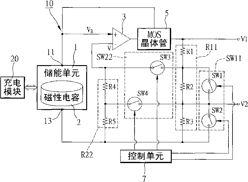
[0036] The power supply device proposed by the present invention uses a magnetic capacitor to replace the voltage source in the general power supply device, so as to increase the capacity of each energy storage and reduce the number of charging and discharging, thus simplifying the circuit structure and reducing the cost.

[0037] The main technical feature of the present invention is that a magnetic capacitor is used as the voltage source of the power supply device. The following only proposes the necessary system structure. However, those skilled in the art should know that, in addition to the components mentioned below, the power supply device certainly includes Other necessary components and aspects, therefore, should not be limited to those disclosed in this embodiment.

[0038] First, see figure 1 , which is a system structure diagram of a specific embodiment of the power supply device disclosed in the present invention. Such as figure 1 As shown, the power supply devi...


PUM


Abstract

The invention discloses a power supply device which comprises an energy storage unit, a first resistance network, a first switching unit and a control unit. The energy storage unit comprises at least one magnetic capacitor, and the magnetic capacitor is provided with a first end and a second end, wherein a reference voltage is provided for the energy storage unit from the first end; the first resistance network is coupled between the first end and the second end; the first switching unit is coupled to the first resistance network; and the control unit is coupled to the first switching unit and used for controlling the state of the first switching unit, wherein the power supply device divides the reference voltage and outputs a plurality of operating tensions according to the conducting state of the first switching unit.

Description

technical field [0001] The invention relates to a circuit, in particular to a power supply device. Background technique [0002] Most of the current power supply devices are equipped with a voltage divider circuit to output multiple voltages. A general voltage divider circuit needs to have a voltage source that provides power, such as a battery. Load use, and avoid excessive current flowing through the circuit and damage the circuit. However, although the batteries used in the market are advertised as being reusable, they still have a limited lifespan. In the case of repeated charging and discharging or long-term non-use, the capacity of the battery will decrease and it will be easily damaged. The reason is that the battery uses chemical energy to convert into electrical energy. When the activity of all the compounds is used up or nearly used up, new chemical reactions can no longer be carried out, which leads to the aging of the battery and the end of its life. [0003] ...

Claims


Application Information

Patent Timeline
IPC IPC(8): H02J15/00H01G4/008
Inventor 唐德铭
Owner LITE ON TECH CORP
Why Eureka
Try Eureka