Flow forwarding method, devices and system

A traffic forwarding and traffic technology, applied in the network field, can solve the problems of uncontrollable outside world, unbalanced uplink traffic, large investment, etc., and achieve the effect of improving the carrying capacity

Inactive Publication Date: 2010-06-09
NEW H3C TECH CO LTD
View PDF0 Cites 40 Cited by
  • Summary
  • Abstract
  • Description
  • Claims
  • Application Information

AI Technical Summary

Problems solved by technology

[0007] The disadvantage of this method is that IRF stacking technology is generally used for equipment expansion, and after each access switch is stacked, it performs full forwarding internally, that is to say, when traffic is forwarded, the traffic on the stacking line will be very large. Generally, optical fibers or dedicated stacking cables are required, and the investment is relatively large; figure 2 The two traffic flows are forwarded from the access switch A to the aggregation switch through the HASH algorithm
In addition, since the devices that can be stacked together must h

Method used


Image

  • Flow forwarding method, devices and system
  • Flow forwarding method, devices and system
  • Flow forwarding method, devices and system

Examples


Embodiment Construction

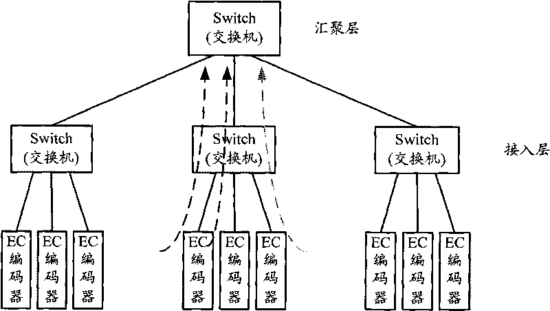
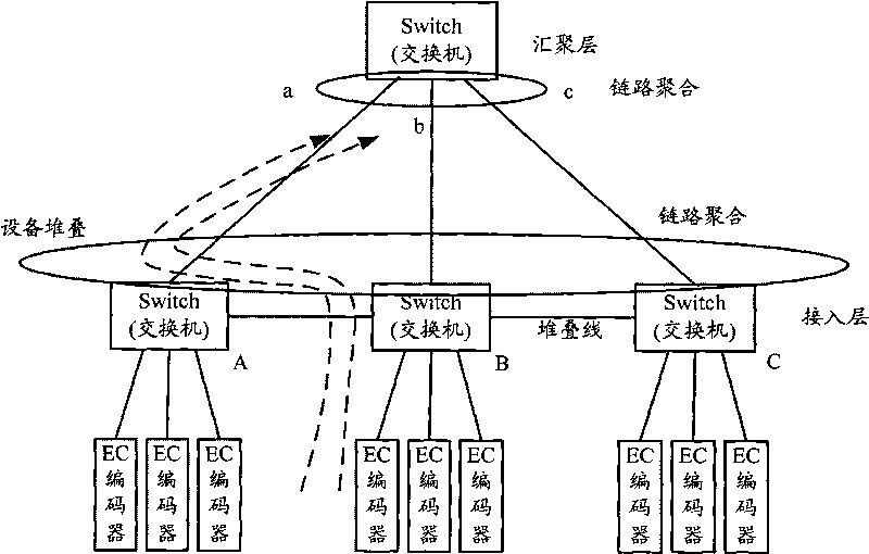
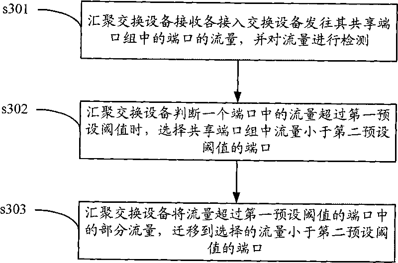
[0040]The present invention provides a flow forwarding method, which is applied to a network system including at least one convergence switching device at the convergence layer and multiple access switching devices at the access layer. The switching devices are connected as a chain device group, the aggregation switching device is connected to each access switching device, and the ports connected to multiple access switching devices are added to a shared port group, and the aggregation switching device Traffic migration between ports implements flow control, so that each access switching device shares the uplink between the aggregation switching devices, thereby improving the carrying capacity of traffic bursts. Specifically, such as image 3 As shown, the method includes the following steps:

[0041] Step s301, the aggregation switching device receives the traffic sent by each access switching device to the port in its shared port group, and detects the traffic;

[0042] St...


PUM


Abstract

The invention discloses flow transmitting method, devices and system. The method comprises the following steps of: receiving port flows sent by each access switching device to a shared port group of a convergence switching device by the convergence and exchange device and detecting flows; when the convergence and exchange device judges the flow in a port exceeds a first preset threshold value, selecting ports with flows being smaller than a second threshold value in the shared port group; and migrating partial flows of ports with the flows exceeding the first preset threshold value to the selected ports with the flows being smaller than the second preset threshold value by the convergence switching device. A plurality of access switching devices are connected by the invention and share an uplink between the access switching devices and the convergence switching device, and flow control is realized through the flow migration among the ports by the convergence switching device, thereby further improving the loading capacity of the system to flow emergencies.

Description

technical field [0001] The present invention relates to the field of network technology, in particular to a flow forwarding method, device and system. Background technique [0002] In the prior art, when a multimedia terminal accesses a network, a typical network structure is as follows: figure 1 shown. Multiple terminals must be connected to each access switch located at the access layer. In the scenario of monitoring access, the terminal can be an encoder EC (Encoder) ( figure 1 Take the monitoring scenario as an example); in the scenario of video products, the terminal can be a multimedia gateway, and the video stream reaches the aggregation switch at the aggregation layer through the access switch at the access layer. Regardless of the terminal in any scenario, there will be traffic bursts in the video stream. Traffic burst means that the traffic needs to occupy a relatively large bandwidth in an instant. The main causes include: image motion, inconsistent size of I f...

Claims


Application Information

Patent Timeline
IPC IPC(8): H04L12/56H04L12/04H04L12/801
Inventor 任俊峰周迪
Owner NEW H3C TECH CO LTD
Why Eureka
Try Eureka