Method and apparatus for die casting of parts

一种压模、零件的技术,应用在运输和包装、薄料处理等方向,能够解决损失速度和压力、零件密度不均匀、冷却等问题

Inactive Publication Date: 2010-06-09
INTERPLEX IND
View PDF1 Cites 3 Cited by
  • Summary
  • Abstract
  • Description
  • Claims
  • Application Information

AI Technical Summary

Problems solved by technology

Similar to the conventional method mentioned earlier, as the molten material travels up through the sprue and into the gate, it cools and loses velocity and pressure, resulting in the same type of defects when casting smaller, more complex parts
Another problem with this method is that when the melt enters the higher gate it is cooler than when it enters the lower gate because it has to travel a longer distance, resulting in uneven density of the part and poor microstructure

Method used


Image

  • Method and apparatus for die casting of parts
  • Method and apparatus for die casting of parts
  • Method and apparatus for die casting of parts

Examples


Embodiment Construction

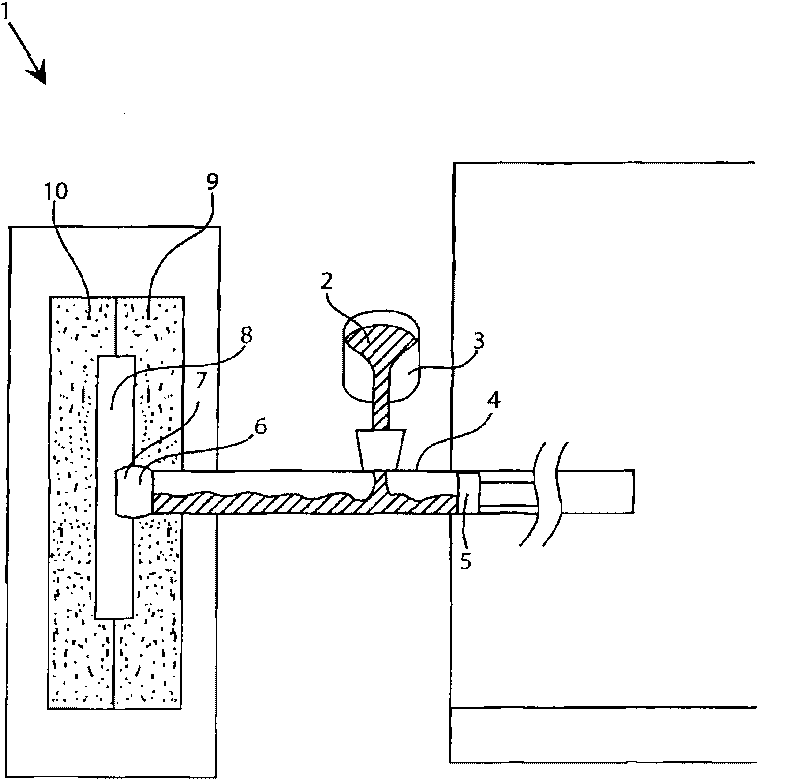
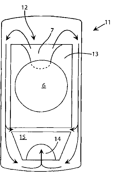
[0015] figure 1 A side view of a cold chamber die casting machine according to the invention is shown, generally designated 1, figure 2 The inner disc mold 6 , runners 7 and gate openings 12 or passages of the present invention are shown attached to the finished part 11 . Molten material 2 , usually aluminium, is poured via telescoping box 3 into injection channel 4 . Next, the die punch 5 forces the melt or molten material 2 into the mold cavity 8 through at least one gate opening 12 located near the upper part of the inner disc mold 12 . Initially the punch 5 starts moving towards the mold cavity 8 at a lower speed, and then, as it gets closer to the area where the inner disk mold 6 is to be formed, the punch accelerates the molten material 2 at a higher speed. This is done to prevent turbulence in the molten material 2 which could cause flow lines, bubbles or other defects in the final product. The mold halves 9 and 10 forming the inner mold cavity 8 are clamped togeth...


PUM


Abstract

A cold-chamber die-casting apparatus and method for making a die-cast part with an open space within the geometry of the part. The apparatus includes an injection shaft which receives molten material for casting the part. The molten material is pushed with a plunger through a gate and into a tool cavity corresponding to the part. The gate is disposed at an end of the injection shaft and adjacent the tool cavity at a position that corresponds to the open space of the part and is inside the geometry of the part.

Description

[0001] Cross References to Related Applications [0002] This application claims priority under 35 U.S.C. §119 to U.S. Provisional Application Serial No. 60 / 948,668, filed July 9, 2007, which is hereby incorporated by reference in its entirety. technical field [0003] The present invention relates to die casting and, in particular, to methods and apparatus for cold chamber die casting of relatively thin-walled parts having features for receiving, for example, display panels or keypads within the part geometry. open space. Background technique [0004] Die casting has long been known as a method of forming parts with complex geometries and / or surface decorations. In the past, die casting of aluminum parts was a common technique in the automotive industry, and many of the known methods were derived from the needs of automotive manufacturers. Recently, there has been a need in the mobile phone and electrical appliance industries to manufacture smaller, more complex aluminum ...

Claims


Application Information

Patent Timeline
Patent Type & Authority Applications(China)
IPC IPC(8): B22D17/08
CPCB22D17/10Y10T428/12
Inventor 李根姬李峰基
Owner INTERPLEX IND
Why Eureka
Try Eureka