Moving mechanism and blocking buckle mechanism thereof

A technology of moving mechanism and locking parts, which is applied to furniture parts, household utensils, drawers, etc., and can solve problems such as collision objects and falling

Inactive Publication Date: 2010-06-16
INVENTEC CORP
View PDF0 Cites 2 Cited by
  • Summary
  • Abstract
  • Description
  • Claims
  • Application Information

AI Technical Summary

Problems solved by technology

[0003] However, when moving the cabinet, since the drawer can slide, it is easy...

Method used


Image

  • Moving mechanism and blocking buckle mechanism thereof
  • Moving mechanism and blocking buckle mechanism thereof
  • Moving mechanism and blocking buckle mechanism thereof

Examples


Embodiment Construction

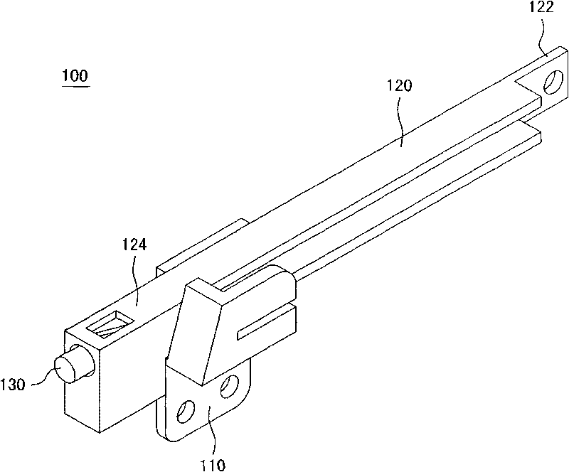
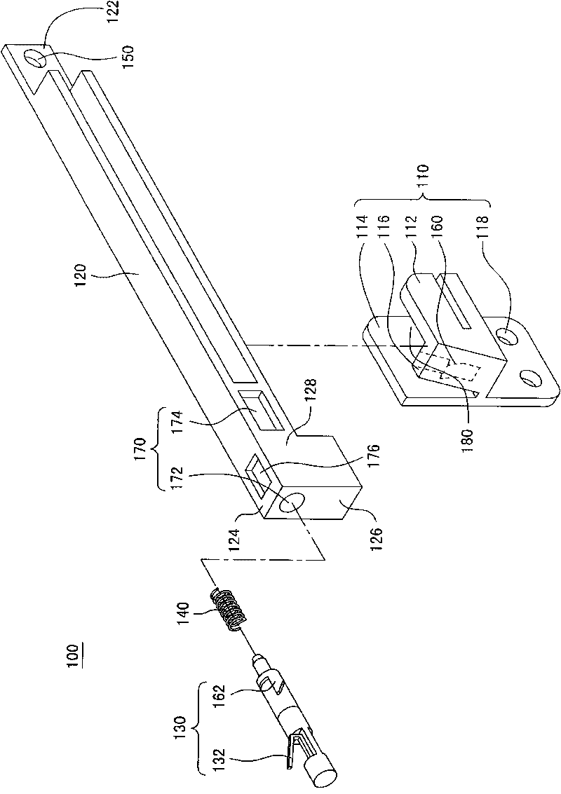
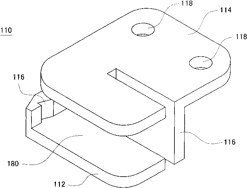
[0037] Please also refer to figure 1 and figure 2 . figure 1 and figure 2 It is a perspective view and an exploded view of the buckle mechanism 100 according to an embodiment of the present invention. The locking mechanism 100 includes a fixing part 110 , a rotating rod 120 and a locking part 130 . The fixing member 110 can be fixed on an object such as a casing (not shown). The rotating rod 120 is used to traverse the moving path of the slider (not shown) to block the movement of the slider. The first end 122 of the rotating rod 120 can be pivotally connected to the casing so as to rotate relative to the fixing member 110 . The locking member 130 is connected to the second end 124 of the rotating rod 120 and can be used to lock the rotating rod 120 and the fixing member 110 .

[0038] The rotating rod 120 is approximately rod-shaped, and the center of the rod body can be used to block the sliding part. The first end 122 of the rotating rod 120 is pivotally connected ...


PUM


Abstract

The invention relates to a blocking buckle mechanism, which comprises a rotating rod, a fixed component and a lock catch component. The first end of the rotating rod is pivoted with a shell so as to rotate by taking the first end as a centre; the second end of the rotating rod is provided with a groove; the first opening and the second opening of the groove are respectively positioned on a pair of adjacent planes of the rotating rod; the fixed component is fixed on the shell and is provided with a first clamping structure; the lock catch component is accommodated in the groove and is protruded out of the first opening partially; the lock latch component is provided with a second clamping structure; when the rotating rod rotates to enable that the second end is contacted with the fixed component, the first clamping structure is aligned with the second opening; and the second clamping structure passes through the second opening to be connected with the first clamping structure so as to lock the rotating rod with the fixed component fixedly. The invention also discloses a moving mechanism with the blocking buckle mechanism.

Description

technical field [0001] The present invention relates to a moving mechanism, and in particular to a buckle mechanism for preventing sliding. Background technique [0002] The moving mechanism is widely used in places such as machine tables, cabinets, sliding doors, etc. For cabinets, slide rails are generally arranged inside the cabinet body, and drawers are mounted on the slide rails. Through the slide rails, the drawers can be easily pulled out or pushed into the cabinet. [0003] However, when moving the cabinet, since the drawer is slidable, it is easy to slide out during the moving process, and then fall or collide with surrounding objects. [0004] In view of this, there is a need for a new moving mechanism and a catch mechanism thereof, which can hold objects so that they cannot slide, or untie objects so that they can slide. Contents of the invention [0005] The technical problem to be solved by the present invention is to provide a new moving mechanism and its ...

Claims


Application Information

Patent Timeline
IPC IPC(8): A47B88/16A47B88/04
Inventor 官长明
Owner INVENTEC CORP
Why Eureka
Try Eureka