Planetary mixer

A planetary mixer and mixing head technology, used in mixer accessories, mixers with rotary mixing devices, mixers, etc., can solve the problems of oil leakage, oil leakage economy, loss, etc., and achieve the effect of preventing leakage

Active Publication Date: 2010-06-16
INOUE SEISAKUSHO MFG
View PDF1 Cites 2 Cited by
  • Summary
  • Abstract
  • Description
  • Claims
  • Application Information

AI Technical Summary

Problems solved by technology

Lubricating oil leaks like this, and the lubricating oil will be mixed into the product, so it must be carefully ope

Method used


Image

  • Planetary mixer
  • Planetary mixer
  • Planetary mixer

Examples


Example Embodiment

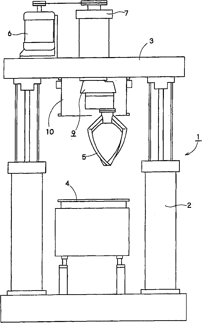
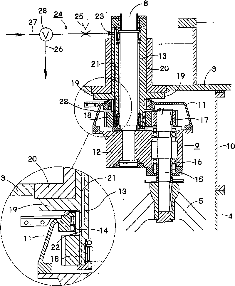
[0012] The present invention can be applied to various planetary mixers, such as figure 1 As shown, the planetary mixer body 1 has a stirring head 3 that is lifted and lowered by the lifting pressure cylinder 2, and the blades 5 are arranged to be inserted into the stirring tank 4 when the stirring head 3 descends. The stirring head 3 is provided with a drive shaft 8 ( figure 2 ), a rotor 9 is connected to the lower end of the drive shaft 8 , and the blades 5 are mounted on the rotor 9 . A shield 10 surrounding the rotor 9 is formed on the lower surface of the stirring head 3 , and the shield 10 can cover the upper surface of the stirring tank 4 as well known.

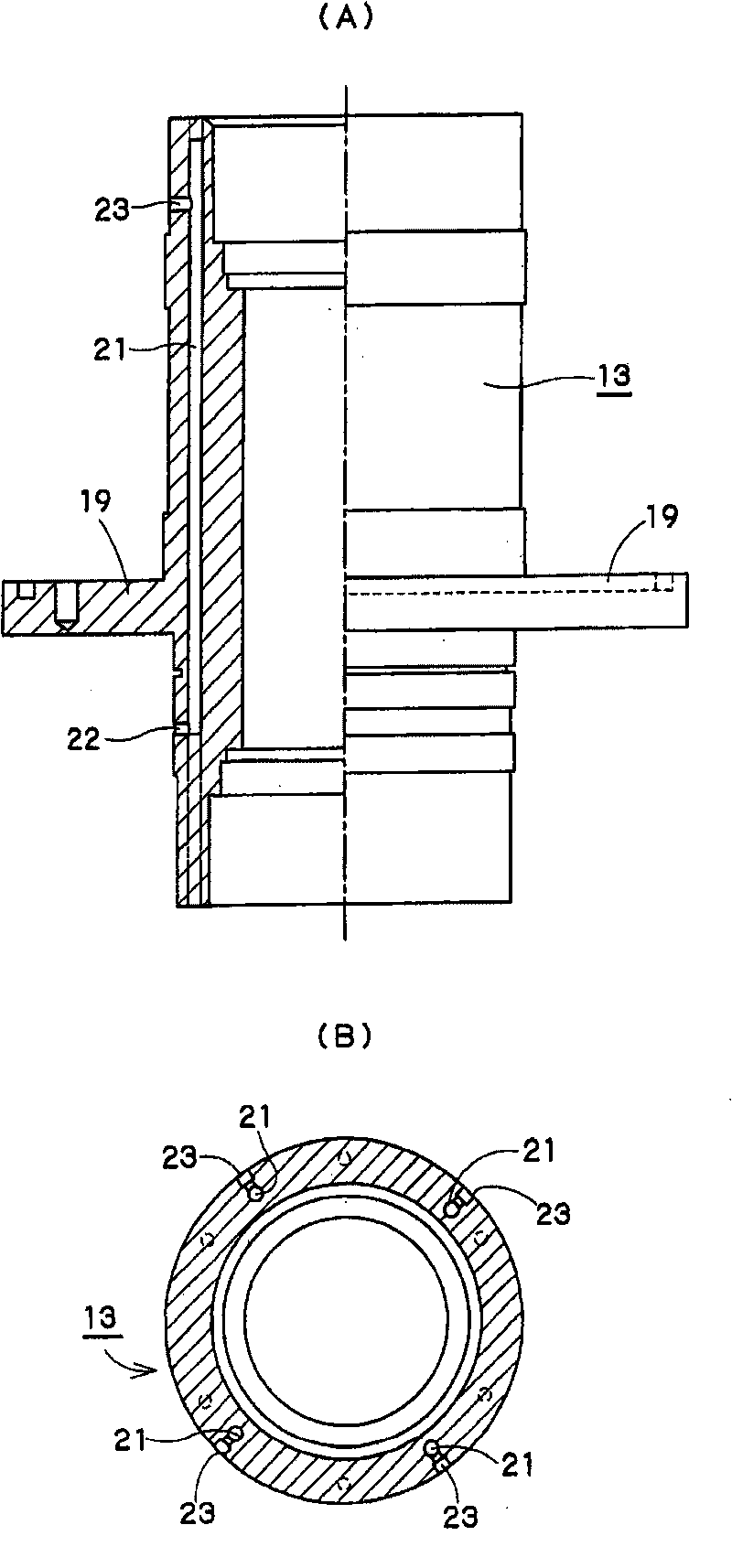
[0013] The rotor 9 includes a gearbox 11 that accommodates a drive member for planetary motion of the vanes 5 , and a bearing housing 12 for a vane shaft that is airtightly connected below the gearbox 11 . like figure 2 As shown, the gear box 11 is connected to the lower part of a support cylinder (bearing cover) ...


PUM


Abstract

The present invention provides a planetary mixer. After a mixing tank is covered by a shield, and the processings of heating, pressurizing, vacuum depressuring, etc. are performed for the inner part, the leakage of lubrication oil sealed in a rotor is prevented when the inner part of the mixing tank is opened to atmosphere. A rotatable rotor (9) is provided at the lower part of a supporting barrel (13) fixed to a mixing head (13). The supporting barrel (13) is provided with a ventilation path (21) for communicating the inner part of the rotor (9) with the outer part. The outer opening end (23) of the ventilation path (21) is provided with a pressure relief valve (28) communicated with with atmosphere.

Description

technical field [0001] The present invention relates to a planetary mixer for kneading materials to be processed by planetary motion of blades in a mixing tank. Background technique [0002] In the past, as a kneading type disperser used for dispersing, stirring, kneading, etc. from low viscosity to high viscosity (~3000Pa·s) or semi-solid processed materials, multiple blades were used in the stirring tank. A planetary mixer with planetary motion is already known (for example, refer to Patent Document 1). Generally speaking, in this planetary mixer, a drive shaft is installed on a liftable stirring head, and a rotor containing driving components such as gears for planetary motion of the blade shaft is installed below it, and the stirring head is lowered to be installed on the planetary mixer. The blade at the lower end of the blade shaft is inserted into the stirring tank, and the rotor is driven to rotate by the drive shaft so that the blade performs planetary motion. At ...

Claims


Application Information

Patent Timeline
IPC IPC(8): B01F7/30
CPCB01F27/2322B01F27/806B01F27/95B01F2035/353B01F2035/99
Inventor 井上芳隆长井圣二是石芳辉
Owner INOUE SEISAKUSHO MFG
Why Eureka
Try Eureka