
Device for eliminating flying lateral force of aircraft at high angle of attack

An aircraft with a large angle of attack technology, applied in the aerospace and weapon industries, aviation fields, can solve the problems of complex mechanism, large model changes, inconvenient model head placement, etc., to eliminate lateral force, reliable performance, simple structure. Effect

Inactive Publication Date: 2010-06-16
NORTHWESTERN POLYTECHNICAL UNIV
View PDF0 Cites 3 Cited by
  • Summary
  • Abstract
  • Description
  • Claims
  • Application Information

AI Technical Summary

Problems solved by technology

[0004] At present, there are mainly the following measures to control the asymmetric vortex at high angle of attack: 1) Holes are drilled in the head of the model, and the lateral force is controlled by the control method of pulsating air blowing through small holes. The main disadvantage is the control of the asymmetric vortex. The required blowing volume is closely related to the incoming flow velocity, that is to say, as the flight speed increases, the blowing volume also increases accordingly, so the required energy also increases, and the weight cost of additional equipment is relatively high; 2) Put the model head It is transformed into a movable nose cone, which is controlled by the left and right deflection (or rotation) of the nose cone. Obviously, the mechanism of this method is complicated, and the changes to the model are relatively large; Realize the forced vibration of the shimmy mechanism and realize the control of the asymmetrical vortex with less energy consumption. According to the results in the literature, the effect of this control method is very good, but the small disturbance shimmy mechanism is still very complicated, requiring power supply and control The weight of the mechanism is also expensive, and sometimes it is not convenient to place in the limited space on the head of the model

Method used


Image

  • Device for eliminating flying lateral force of aircraft at high angle of attack
  • Device for eliminating flying lateral force of aircraft at high angle of attack
  • Device for eliminating flying lateral force of aircraft at high angle of attack

Examples


Embodiment Construction

[0021] This embodiment is a device that can eliminate the lateral force of the aircraft at a high angle of attack, including a film support frame and a retractable mechanism.

[0022] as attached figure 1 As shown, the self-excited diaphragm of the present embodiment is installed above the aircraft head. The self-diaphragm realizes its deployment and retraction by rotating in the plane of the symmetry axis of the aircraft through the center of rotation arranged at the tip of the head.

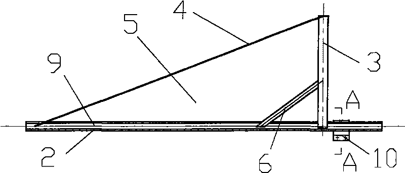
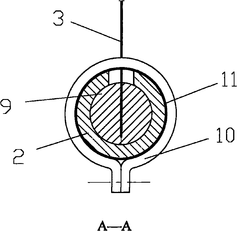
[0023] like figure 2 and image 3 shown. The film supporting frame includes a film 5 , a support reed 3 , a brace reed 6 , a film reinforcing rib 4 , a clamping core 9 , a sleeve 2 and a clamping hoop 10 . in:

[0024] The shape of the film 5 is a right triangle, and the vertex angle of the film 5 is equal to 2 / 3 of the cone angle of the aircraft head. The film reinforcing rib 4 that useful rubber band is made on film 5 hypotenuses. One straight side of the film 5 is bonded with a suppo...


PUM


Abstract

The invention relates to a device for eliminating the flying lateral force of an aircraft at a high angle of attack, which comprises a thin film support frame and a retraction and extension mechanism. A retraction and extension seam is formed on a skin over the front part of the head part of the aircraft; a hinge (12) is fixedly arranged at the zenith of the head part in the aircraft, and the center of the hinge is positioned on the axial line of the aircraft; the thin film support frame is mounted in the aircraft, and the thin film support frame is positioned on the longitudinal symmetric plane of the aircraft; and the zenith end of a triangle of the thin film support frame is connected with the hinge (12) at the zenith of the head part of the aircraft, and can rotate around the center of the hinge (12). When the aircraft flies within the flying range of the high angle of attack, the thin film support frame is popped up, a film chip realizes the self-excited vibration in airflow, produces the unsteady flow around the film chip and realizes the control of asymmetric vortex, thereby eliminating the lateral force; when the aircraft recovers the small angle of attack state, the retraction and extension mechanism retracts the support frame into a front body of a slender body. The device is applicable to the aircrafts with the head taper of less than 42 degrees and characterized by simple structure and reliable performance.

Description

technical field [0001] The invention relates to aviation, spaceflight and weapon industry, and is a device for eliminating the lateral force of an aircraft at a high angle of attack. Background technique [0002] When aircraft such as fighter jets or tactical missiles fly at high angles of attack, the flow in the leeward region of the aircraft is composed of some vortices with asymmetric strength and position. many unfavorable factors. How to eliminate these lateral forces by regulating the asymmetric vortex of the precursor is a technical difficulty that aerodynamicists and scientific research institutions have been working hard to study. [0003] In the range of small angles of attack (0°≤α<10°), the flow around the model is a stable flow with no lateral force; in the range of small and medium angles of attack (10°<α≤20°), the model flow Separation occurs, and a pair of symmetrical vortices with opposite rotation are rolled up in the leeward region of the model. Th...

Claims


Application Information

Patent Timeline
IPC IPC(8): B64C13/28
Inventor 张伟伟刘小波宋述芳叶正寅
Owner NORTHWESTERN POLYTECHNICAL UNIV
Learn More