Hydraulic driving device applied to molded surface forming of wind tunnel nozzle

A driving device and surface forming technology, applied in the direction of measuring device, aerodynamic test, machine/structural component test, etc., can solve the problems of drive mechanism damage, small space size, processing, installation and motion errors, etc., to avoid Effects of destructive effects, improvement of driving ability, and improvement of service life

Active Publication Date: 2021-06-29
中国空气动力研究与发展中心设备设计与测试技术研究所
View PDF16 Cites 3 Cited by
  • Summary
  • Abstract
  • Description
  • Claims
  • Application Information

AI Technical Summary

Problems solved by technology

Obviously, with the increase of the size of the wind tunnel and the increase of the Mach number, it is difficult for the electric drive form to meet the forming requirements of the nozzle section of the large continuous transonic wind tunnel.
In order to improve the driving force of the actuator, the hydraulic drive form with high-density driving capability has become a solution to the problem, but there are several problems to be solved in the following aspects: On the one hand, the cross-sectional dimension of the nozzle surface of the wind tunnel (perpendicular to The airflow direction) is relatively large, and a good synchronous driving force is required along the cross-sectional direction to form a two-dimensional profile with the required Mach number; on the other hand, in order to improve the forming accuracy of the profile, it is necessary to The driving devices are arranged in many places, and the driving device is required to have a large driving force while the space size should be as small as possible; in addition, due to certain errors in the processing, installation and movement of the molding system, lateral forces will be generated inside the molding system, and in severe cases , will have a destructive effect on the drive mechanism

Method used


Image

  • Hydraulic driving device applied to molded surface forming of wind tunnel nozzle
  • Hydraulic driving device applied to molded surface forming of wind tunnel nozzle
  • Hydraulic driving device applied to molded surface forming of wind tunnel nozzle

Examples


Embodiment

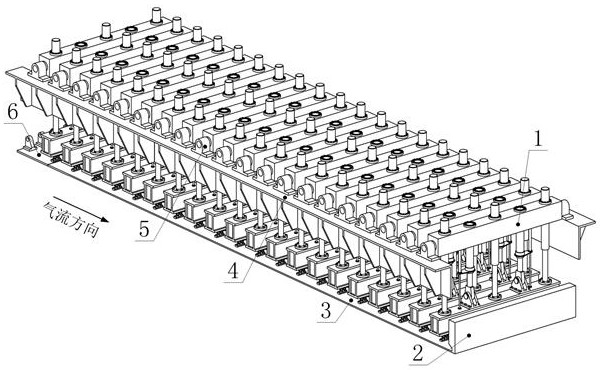
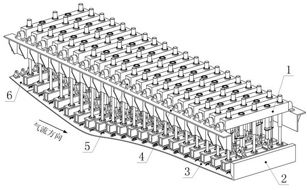
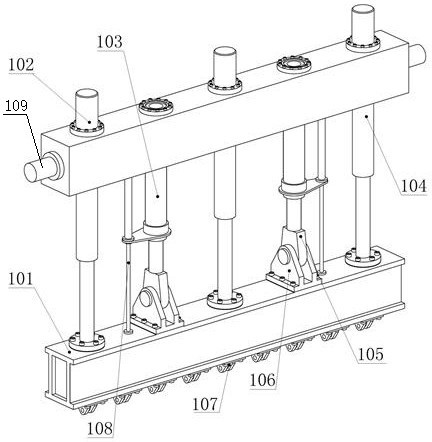
[0025] It can be seen from the drawings that in this embodiment, the profile of the wind tunnel nozzle includes a flex plate, a flex plate support frame, and a profile compensation mechanism; one end of the flex plate is connected to the flex plate support frame, and the other end of the flex plate is connected to the profile The compensation mechanism is connected; a support frame is set above the flex plate; several hydraulic drive devices connected with the flex plate are set on the support frame along the airflow direction; the hydraulic drive device includes an upper beam, a lower beam, a guide mechanism and a hydraulic drive mechanism; the guide The mechanism and the hydraulic drive mechanism are fixed on the upper beam and fixedly connected with the upper end surface of the lower beam.

[0026] A flexible plate hinge seat is provided on the upper end surface of the flexible plate; a flexible plate hinge is provided on the lower end surface of the lower beam; the flexible...


PUM


Abstract

The invention discloses a hydraulic driving device applied to wind tunnel nozzle profile forming. The hydraulic driving device comprises a lower cross beam, an upper cross beam, a hydraulic driving mechanism, a guide mechanism, a spherical hinge hanging ring head, a push rod hinge base, a flexible plate hinge and a linear displacement sensor. The multiple hydraulic driving mechanisms and the multiple guiding mechanisms are symmetrically installed on the upper cross beam and connected with the lower cross beam, and the driving function and the guiding function are integrated. In the wind tunnel nozzle profile forming process, a plurality of hydraulic oil cylinders with small driving force can be combined into a large-load driving device required by accurate forming of a large wind tunnel nozzle, and the influence of lateral force on the oil cylinders is eliminated by utilizing the guide mechanism, so that large-load driving can be realized by utilizing the small hydraulic oil cylinders; and the reliability and the service life of the device are improved.

Description

technical field [0001] The invention relates to the field of large-scale continuous transonic wind tunnel structure design, in particular to a hydraulic drive device applied to the profile forming of a wind tunnel nozzle. Background technique [0002] The quality of the flow field is an important index to measure the performance of the wind tunnel, and the nozzle section is the core section of the wind tunnel, which directly affects the flow field of the wind tunnel test. In order to realize the adjustment of the Mach number and ensure the quality of the flow field at different Mach numbers, it is necessary to carry out precise shaping control on the profile of the nozzle section to adjust the Mach number and uniformity of the flow field in the test area. Large-scale continuous transonic wind tunnels generally adopt multi-support and multi-drive semi-flexible or fully flexible-wall nozzles, which have the characteristics of large structural size, large load, and high require...

Claims


Application Information

Patent Timeline
Patent Type & Authority Applications(China)
IPC IPC(8): G01M9/04
CPCG01M9/04Y02E10/72
Inventor 廖文林张浩陈振华王超琪张志秋刘念
Owner 中国空气动力研究与发展中心设备设计与测试技术研究所
Why Eureka
Try Eureka