Arm pin structure of suspension arm and arm pin assembly and disassembly mechanism thereof

A disassembly mechanism and arm pin technology, applied to cranes, hand-held tools, manufacturing tools, etc., can solve the problems of crane user loss, arm pin spring not fully reset, safety hazards, etc., to achieve low labor intensity and simple mechanism structure , The effect of ensuring reliability

Active Publication Date: 2010-06-16
ZOOMLION HEAVY IND CO LTD
View PDF0 Cites 5 Cited by
  • Summary
  • Abstract
  • Description
  • Claims
  • Application Information

AI Technical Summary

Problems solved by technology

[0017] The inventor found that the second scheme has a fatal hidden danger for the safety of the whole vehicle. Since the thread pair can realize self-locking at any position, its application in this arm pin scheme brings benefits and also exists It is a big disadvantage, and the specific reasons are as follows: When the arm pin spring needs to be reset, if the operator does not understand the specific operation essentials of the structure or makes an operation error and the screw rod is not fully screwed in place, the arm pin spring will not be fully reset to the original position. working length
[0018] That is to say, the arm pin cannot rise to the limit working position when it is working. At this time, once the crane starts to lift the weight, the deflection of the boom will become larger under the action of the heavy objects. The clearance of the boom will increase accordingly. Since the boom pin cannot rise t...

Method used


Image

  • Arm pin structure of suspension arm and arm pin assembly and disassembly mechanism thereof
  • Arm pin structure of suspension arm and arm pin assembly and disassembly mechanism thereof
  • Arm pin structure of suspension arm and arm pin assembly and disassembly mechanism thereof

Examples


Embodiment Construction

[0046] The embodiments of the present invention will be described in detail below with reference to the accompanying drawings, but the present invention can be implemented in many different ways defined and covered by the claims.

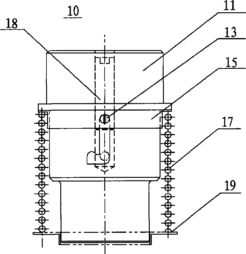
[0047] figure 1 A schematic structural view of an arm pin mechanism according to a preferred embodiment of the present invention is shown. Such as figure 1 As shown, in the embodiment, the arm pin mechanism 10 includes: an arm pin 11 , an arm pin screw 13 , a T-shaped spacer 15 , an arm pin spring 17 , and an arm pin guide rod 18 .

[0048] Wherein, the arm pin guide rod 18 is installed in the axis hole of the arm pin 11, and the end of the threaded hole is on the bottom, and the T-shaped spacer 15 is installed on the supporting section of the arm pin 11, and its shoulder end is on the top to contact with the shoulder of the arm pin. The arm pin spring 17 is sleeved on the supporting section of the arm pin 11, and its upper end surface is in conta...


PUM


Abstract

The invention discloses an arm pin structure of a suspension arm. The arm pin structure comprises an arm pin, a spacer sleeve, a spring, a guide rod and a pin, wherein the arm pin is provided with a centre hole, the wall of the arm pin is provided with a groove penetrating the centre hole; the spacer sleeve is sheathed on the arm pin; one end of the spring is butted with the spacer sleeve; the guide rod is rotatablely arranged in the centre hole of the arm pin; the pin is arranged in the groove of the arm pin and is used to fixedly connect the guide rod and the spacer sleeve; the groove is provided with a positioning part for limiting the extreme position of the pin, and the extreme position of the pin corresponds to the upper extreme position or lower extreme position of the arm pin. The invention has the advantages of high efficiency, low labor strength and the like; in addition, the arm pin only can be in a working state or a compressed state so as to avoid the situation that the arm pin is in a middle state, caused by an accidental operation and safety hazard is caused to affect stability of the axial orientation of the suspension arm. The invention also discloses an arm pin assembly and disassembly mechanism which adopts the lever principle to compress the arm pin spring, thus the time for completing the compression of the arm pin spring is shorter.

Description

technical field [0001] The invention relates to an arm pin mechanism of a boom such as a crane and an arm pin dismounting mechanism for disassembling and assembling the arm pin. Background technique [0002] With the development of crane technology, the length of the boom of the crane is getting longer and longer, and its length has reached 80, 90 meters, or even more than 100 meters. The traditional wire rope telescopic method is no longer applicable, and its telescopic method generally adopts a single cylinder. In the form of bolts, during the hoisting process of the crane, the axial positioning between the arms is no longer in the form of telescopic oil cylinders and wire ropes, but in the form of arm pins. [0003] At the same time, as the tonnage of the crane increases, the quality of its boom is also increasing. The total weight of a set of booms has reached 40 to 50 tons. Due to the limitation of the total weight of the vehicle, it is impossible for the crane to trave...

Claims


Application Information

Patent Timeline
IPC IPC(8): B66C23/62B25B27/02
Inventor 詹纯新刘权邓胜达
Owner ZOOMLION HEAVY IND CO LTD
Why Eureka
Try Eureka