Pressing structure of shaft and shaft hole

A shaft hole and press-in hole technology, applied in the directions of shafts, bearings, shafts, connecting components, etc., can solve the problems of increased driving sound, reduced press-in strength, and shaft skew, so as to reduce press-in skew and reduce impact. , the effect of firmly pressing into the joint

Active Publication Date: 2010-06-16
YAMADA SEISAKUSHO KK
View PDF2 Cites 2 Cited by
  • Summary
  • Abstract
  • Description
  • Claims
  • Application Information

AI Technical Summary

Problems solved by technology

If the chamfer is deepened (increased) along the depth direction of the hole, the above-mentioned problems can be solved, but when the depth of the chamfer is deepened, the depth of the pressed hole becomes shallower accordingly
That is, the effective length of press-fitting is shortened, so the press-fitting strength is reduced
[0019] However, in the techniques disclosed in the aforementioned Patent Documents 1 to 3, the opening diameter of the pulley hole is further increased by chamfering the opening of the pulley hole, and the shaft hole is arranged at the top of the front end of the shaft before the start of press-fitting. When pressure is applied, the shaft tends to be skewed with respect to the center axis of the shaft hole, and the angle of inclination becomes large.
This is because the larger the opening diameter of the end face opening of the shaft hole, the larger the gap between the outer diameter of the front end of the shaft and the opening diameter of the opening of the shaft hole, resulting in looseness, which tends to be further skewed.
[0020] That is, in the shape of the chamfered portion of Patent Document 1 to Patent Document 3, there is an advantage in that press-fitting is easy, but due to the shape of the chamfer, skewing of the shaft is likely to occur, and as a result, as described above, When used as a pulley, etc., there are problems of reduced belt life and increased belt operation noise
Also, conversely, when the inclination angle of the chamfered slope is steepened to reduce the press-fit distortion, the opening diameter of the chamfered end face becomes small, making it difficult to absorb the lateral (diametrical) misalignment of the axis.

Method used


Image

  • Pressing structure of shaft and shaft hole
  • Pressing structure of shaft and shaft hole
  • Pressing structure of shaft and shaft hole

Examples


Embodiment Construction

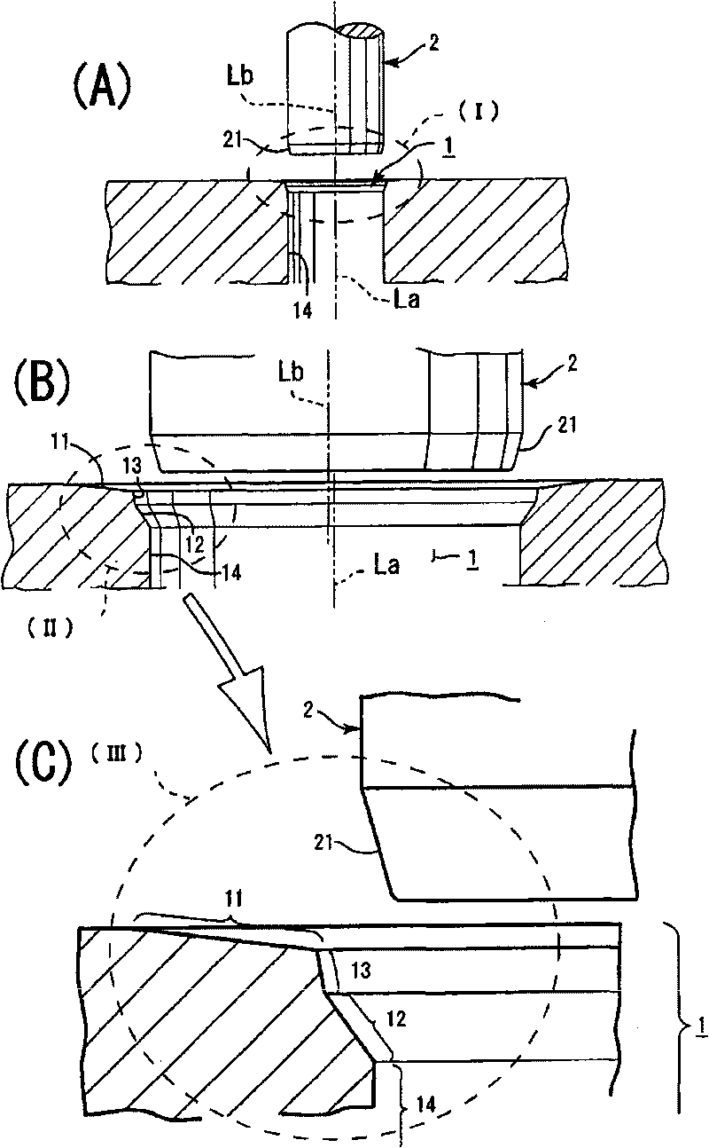
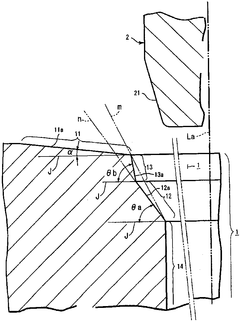
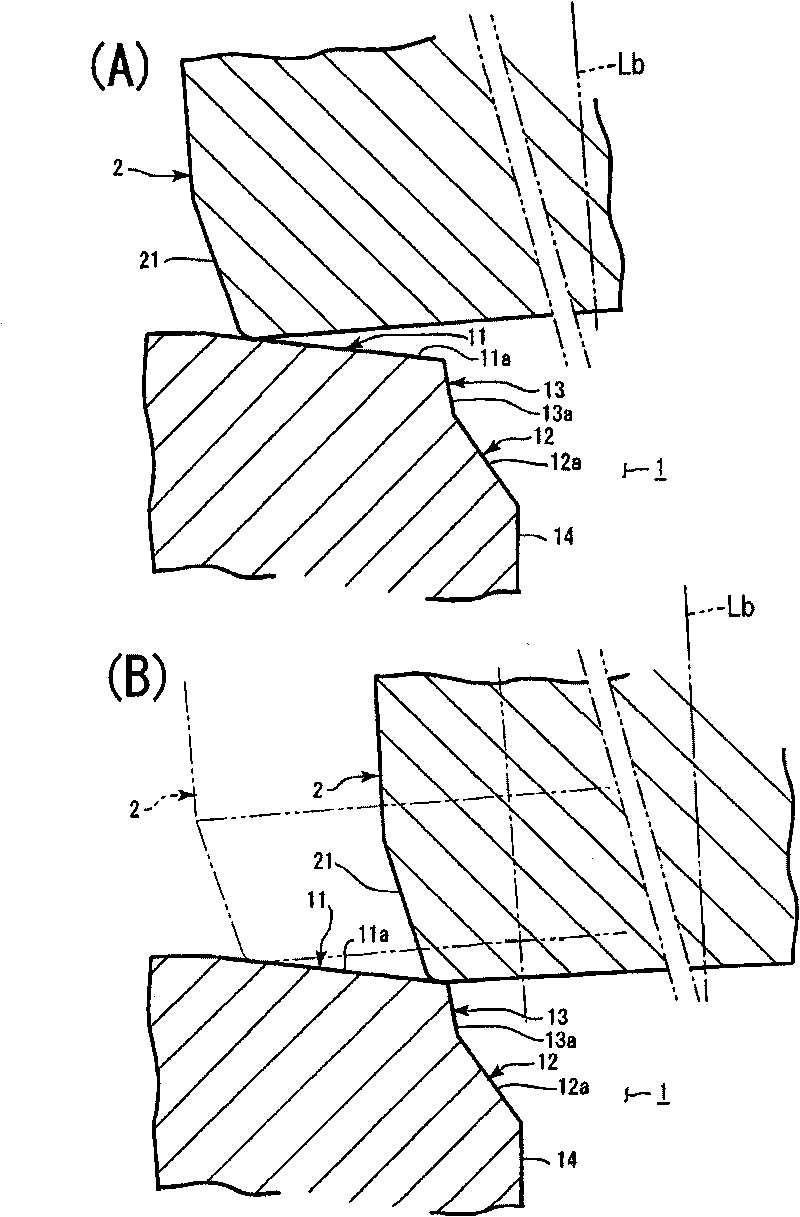
[0042] Embodiments of the present invention will be described below with reference to the drawings. There are many embodiments of the present invention. First, in the first embodiment, if figure 1 As shown, it consists of shaft hole 1 and shaft 2. The shaft hole 1 is arranged on devices such as hub holes of various pumps or wheel hub holes of pulley devices. Such as figure 1 (B), (C) and figure 2 As shown, the shaft hole 1 is composed of an opening end face 11, a slope guide portion 12, a steep slope guide portion 13, and a press-fit hole portion 14. The order of formation is, starting from the opening side of the shaft hole 1, the opening end face 11, the steep slope The guide part 13 , the slope guide part 12 , and the press-fit hole part 14 .

[0043] The diameter center of the opening end face 11 coincides with the diameter center of the slope guide 12, the steep slope guide 13 and the press-fit hole 14 described later [refer to figure 1 (B)]. That is, when an i...


PUM


Abstract

The invention provides a pressing structure of a shaft and a shaft hole, which can accurately press the shaft into the shaft hole with high precision, can fully obtain the pressed-in range, and can realize the firm pressed-in joint. In the shaft (2) and the shaft hole (1) into which the shaft (2) is pressed, the opening end of the shaft hole (1) is formed with an opening end face (11), an inclined plane guiding part (12) expanded toward the opening end is formed at the side of a pressed-in hole part (14) of the shaft hole (1), a steeply inclined plane guiding part (13) expanded from the side of the inclined plane guiding part (12) to the opening end face (11) is formed between the opening end face (11) and the inclined plane guiding part (12). The inclination of the inclined plane of the steeply inclined plane guiding part (13) is more than that of the inclined plane of the inclined plane guiding part (12), and the opening end face (11) is in a flat conical shape.

Description

technical field [0001] The invention relates to a press-fit structure of a shaft and a shaft hole: when the shaft is pressed into the shaft hole, the shaft can be pressed into the shaft hole accurately with extremely high precision, and the press-fit range can be fully obtained, which can Realizes a strong press-fit joint. Background technique [0002] In general in the field of machinery (for example motor vehicles), press-fitting as fastening means in shafts and their shaft bores is generally carried out extensively. As one example, press-fitting of a rod-shaped shaft and a pulley having a hole having an inner diameter slightly smaller than the outer diameter of the shaft is widely performed. As a fastening mechanism for shafts and pulleys, fastening by bolts is widely performed, but fastening by press-fitting is advantageous in terms of manufacturing cost because it is inexpensive. Furthermore, the fastening mechanism by press-fitting can achieve weight reduction by the...

Claims


Application Information

Patent Timeline
IPC IPC(8): F16C3/02F16B4/00
Inventor 岩野功佳
Owner YAMADA SEISAKUSHO KK
Why Eureka
Try Eureka