Motor core riveting device

A technology of iron core and frame, which is applied in the field of riveting devices, and can solve the problems of cumbersome and time-consuming operations

Active Publication Date: 2021-01-05
台州普宇智能科技有限公司
View PDF4 Cites 0 Cited by
  • Summary
  • Abstract
  • Description
  • Claims
  • Application Information

AI Technical Summary

Problems solved by technology

[0004] In the above-mentioned riveting machine, since the position of the iron core itself cannot be rotated, only one rivet can be pressed in in one process, and the operation is cumbersome and time-consuming.

Method used


Image

  • Motor core riveting device
  • Motor core riveting device
  • Motor core riveting device

Examples


Embodiment 1

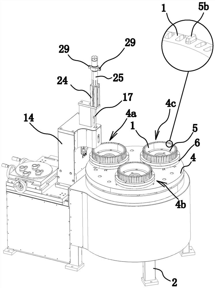
[0056] Such as figure 1 As shown, the motor iron core riveting device is generally composed of a conveying mechanism for conveying the iron core 1 and a pressing mechanism for pressing the rivets 37 into the iron core 1 .

[0057] in,

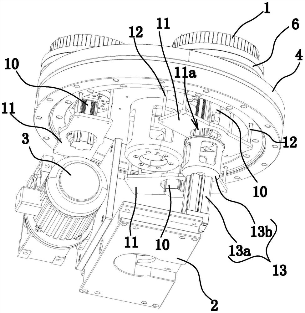
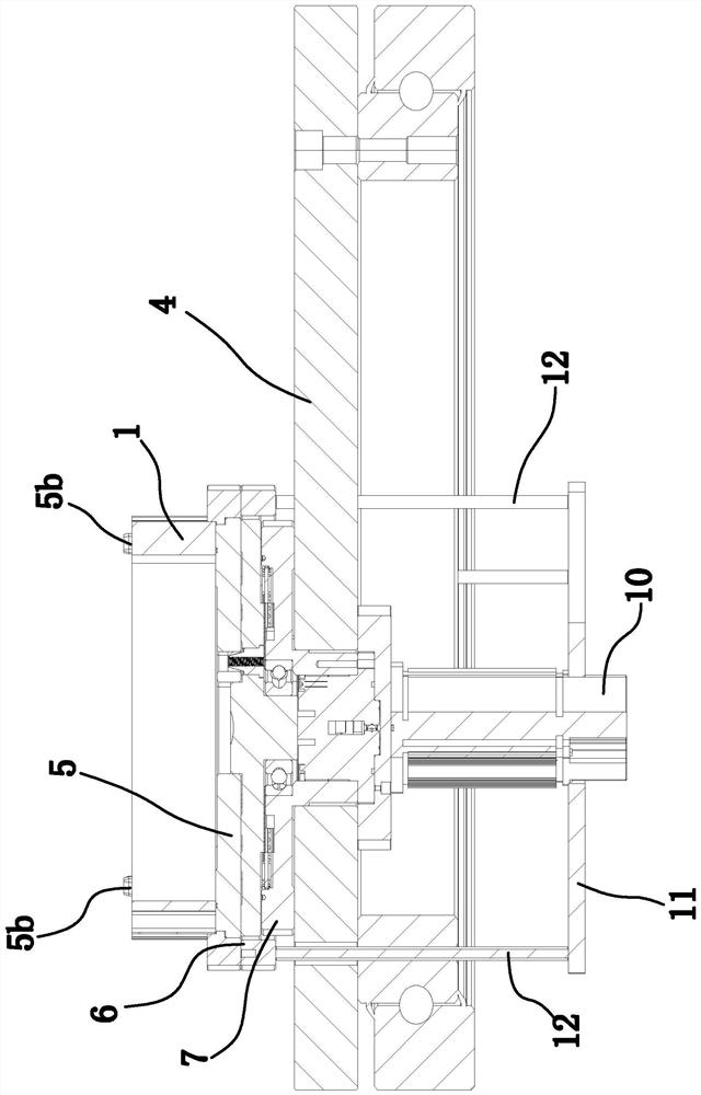
[0058] The conveying mechanism includes a driving mechanism, a frame 2, a motor one 3 fixed on the frame 2, and a turntable 4 horizontally arranged on the frame 2 and driven by the motor one 3 to rotate. A riveting station 4a, a feeding station 4b, and a discharging station 4c are evenly distributed on the turntable 4 in sequence, wherein a pressing mechanism for pressing the rivet 37 into the iron core 1 is provided on one side of the riveting station 4a. The riveting station 4a, the jacking station 4b and the discharging station 4c are all provided with a positioning die 5 that is rotatably connected with the turntable 4 . In this embodiment, the motor one 3 is connected with the turntable 4 through a cam divider, so that the turntable 4 ro...

Embodiment 2

[0081] The structure and principle of this second embodiment are basically the same as that of the first embodiment, except that the driving mechanism includes telescopic cylinders 2 and a connecting frame 32 in the shape of a "concave" that are all located on the lower side of the turntable 4, telescopic cylinders 2 and The quantity of connecting frame 32 is all the same with the top cover 6 and the positions correspond one by one.

Embodiment 3

[0083] The structure and principle of the third embodiment are basically the same as those of the first embodiment, except that the position-limiting structure includes the bottom wall of the top sleeve 6 and the top wall of the turntable 4, and the bottom wall of the top sleeve 6 presses against the top wall of the turntable 4 .


PUM


Abstract

The invention provides a motor iron core rivet pressing device, and belongs to the technical field of machinery. The problem that an existing squeeze riveter is time-consuming in operation is solved.The motor iron core riveting device comprises a rack, a motor I and a turntable which is arranged on the rack and is driven by the motor I to rotate, and a riveting station, a material ejecting station and a discharging station are uniformly distributed on the turntable in sequence; and a press-in mechanism used for pressing rivets into the iron core is arranged on one side of the riveting station. The riveting station, the material ejecting station and the discharging station are each provided with a positioning die rotationally connected with the rotary disc. Each positioning die is providedwith a supporting surface for horizontally supporting the iron core; a vertically arranged linkage rod is arranged on the supporting surface; the linkage rod is provided with at least two pieces of cloth, each positioning die is sleeved with a top sleeve, each top sleeve is provided with an annular face right opposite to the bottom wall of the iron core, motors II used for driving the positioningdies to rotate in the circumferential direction of the iron core are fixed to the lower side of the rotary disc, the number of the motors II is the same as that of the positioning dies, and the motoriron core rivet pressing device further comprises a driving mechanism capable of driving the top sleeves to move vertically. The motor iron core rivet pressing device is high in efficiency.

Description

technical field [0001] The invention belongs to the technical field of machinery, and relates to a riveting device, in particular to a riveting device related to a motor stator core or a rotor core. Background technique [0002] The stator core or rotor core of the motor is made of stacked silicon steel sheets. In order to ensure that the silicon steel sheets are closely matched and not loose, multiple rivets need to be further pierced after being pressed into blocks. [0003] Existing equipment for pressing rivets, such as a motor stator core two-station automatic riveting machine [Application No.: 201510912410.8] disclosed in the Chinese patent library, includes a workbench, and an upper mold mounting plate is fixedly connected to the top of the workbench, and also includes The rotary table is connected with a rotating mechanism under the center of the rotary table. The two ends of the rotary table are the pressing part and the returning part respectively. The pressing par...

Claims


Application Information

Patent Timeline
Patent Type & Authority Patents(China)
IPC IPC(8): H02K15/02
CPCH02K15/02
Inventor 张学斌
Owner 台州普宇智能科技有限公司
Why Eureka
Try Eureka