Valve device

A valve device and valve core technology, applied in valve device, valve operation/release device, fluid pressure actuation device, etc., can solve problems such as increased wear and tear, and achieve the effect of cost saving

Inactive Publication Date: 2010-06-16
费斯托(中国)有限公司 +1
View PDF1 Cites 10 Cited by
  • Summary
  • Abstract
  • Description
  • Claims
  • Application Information

AI Technical Summary

Problems solved by technology

This higher axial magnetic force may increase wear

Method used


Image

  • Valve device
  • Valve device
  • Valve device

Examples


Embodiment Construction

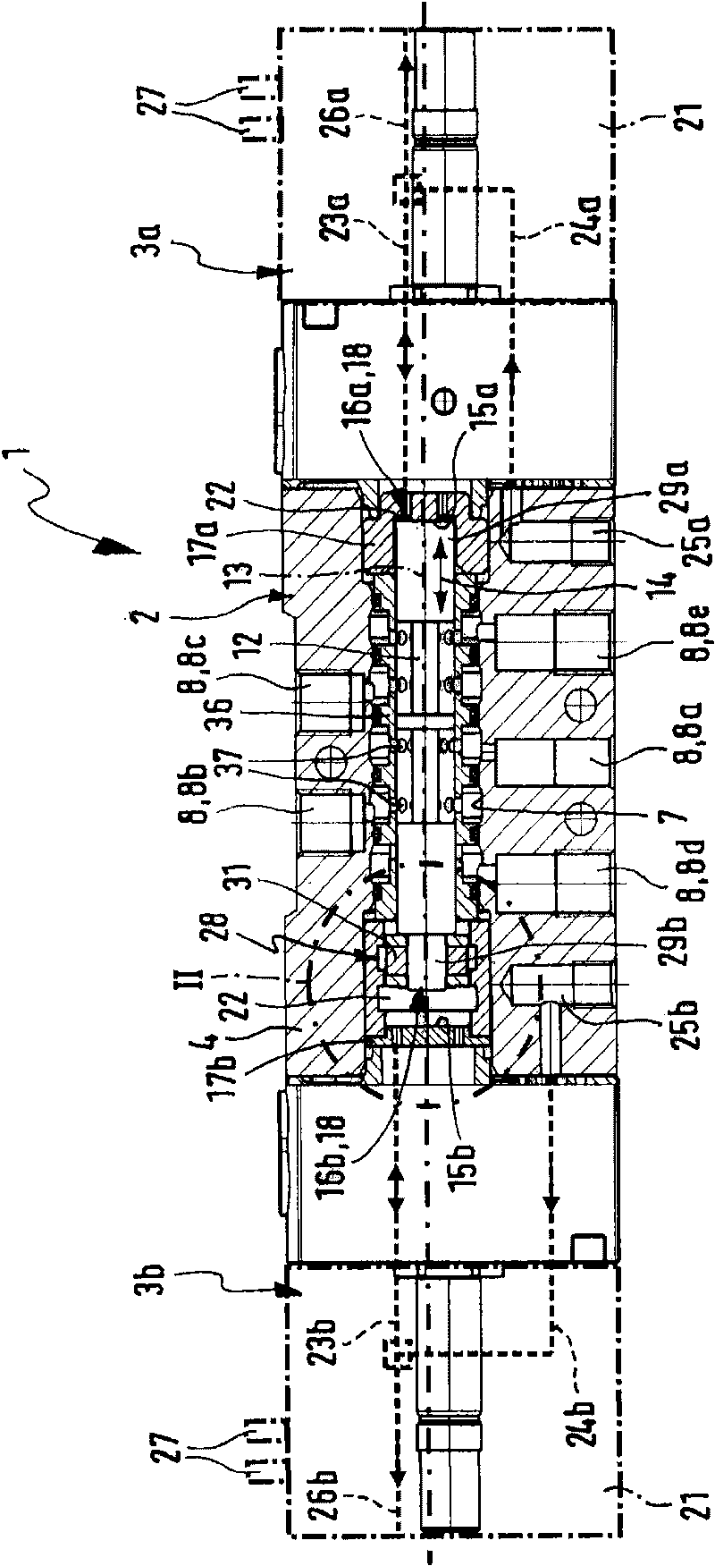
[0028] figure 1 An overall longitudinal section is shown of a valve device 1 according to the invention, which can be called a bistable valve or a pulse valve.

[0029] The valve arrangement 1 comprises a main valve 2 operable by fluid force and two fluid-loaded pilot valves 3a, 3b controlling the main valve 2, the pilot valves 3a, 3b being electrically operable.

[0030] The valve device 1 has a valve housing 4 , on two opposite end faces of the valve housing 4 , one of the two pilot valves 3 a , 3 b is mounted in each case. An elongated receiving chamber 7 extends axially inside the valve housing 4 and is closed at the end by the two pilot valves 3a, 3b.

[0031] A plurality of valve channels 8 extending through the valve housing 4 open into the receiving chamber 7 at lateral axial positions spaced apart from one another. An elongated valve core 12 arranged coaxially with the receiving chamber 7 is located inside the receiving chamber 7 , and the valve core 12 can move axi...


PUM


Abstract

The invention discloses a valve device with a valve core (12), and the valve core can be fixed between two conversion positions with the help of a magnetic latching device (28) which belongs to the end part region of the valve core (12). The magnetic latching device (28) comprises two latching units (32, 33) which are overlapped along the axial direction, one of which is arranged on a valve housing (4), and the other one is arranged on the valve core (12). One of the latching units (32, 33) comprises a permanent magnet (31). First polar surfaces and second polar surfaces (42a, 42b, 42c; 43a, 43b) are arranged on two latching units (32, 33), the first polar surfaces and the second polar surfaces can form different magnetic loops on the two conversion positions of the valve core (12), and the magnetic loops can fix the valve core (12).

Description

technical field [0001] The invention relates to a valve arrangement having an axially movable spool arranged in a receiving chamber of a valve housing, the spool being movable in two axially spaced switching positions by fluid loading during the execution of a switching movement Switching between, the spool is releasably released by means of a magnetic holding device comprising at least one permanent magnet by means of a magnetic force generated by the at least one permanent magnet Stay in the switch position. Background technique [0002] A valve arrangement of this type known from EP 1760376 A1 is designed as a pulse valve. Pulse valves are multi-way valves, the spool of which is actuated in pulses by means of a control pressure of the fluid to switch between two end switching positions, wherein the spool remains in the end switching position after loss of the control pressure. In order to hold the spool in the end position even during oscillation, a holding device is a...

Claims


Application Information

Patent Timeline
Patent Type & Authority Applications(China)
IPC IPC(8): F16K11/07F16K31/42F15B13/04F15B13/043
Inventor 张翼德A·加斯曼
Owner 费斯托(中国)有限公司
Why Eureka
Try Eureka