
Inductive coupling-based anchoring self-lifting profile monitoring buoy

A technology of inductive coupling and profile monitoring, applied in buoys, measuring devices, surveying and navigation, etc., can solve the problems of difficult transmission line design, high cost, and high communication directionality requirements

Inactive Publication Date: 2010-06-16
HANGZHOU DIANZI UNIV
View PDF0 Cites 36 Cited by
  • Summary
  • Abstract
  • Description
  • Claims
  • Application Information

AI Technical Summary

Problems solved by technology

If the communication method between the profiler and the buoy adopts a wired method, the communication distance is constantly changing due to the reciprocating lifting movement of the profiler, which not only makes the design of the transmission line difficult, but also difficult to guarantee the reliability of communication and the safety of the profiler
If the wireless method is adopted, in the underwater wireless communication method, the underwater acoustic communication has a series of advantages such as long transmission distance and high transmission rate, but its cost is too high, and the power consumption is high at the same time. Considering the self-contained power supply of the profiler characteristics, unable to meet long-term observation requirements; underwater laser communication has long communication distance and high transmission rate, but complex structure, high cost, and high communication directionality requirements; underwater LED optical communication has low cost, low power consumption, and long transmission distance It is far away, but there is also the problem of high directionality requirements. If there is no corresponding device to ensure that the probe is aligned within a small range, the communication performance will be greatly reduced or even communication will be interrupted.

Method used


Image

  • Inductive coupling-based anchoring self-lifting profile monitoring buoy
  • Inductive coupling-based anchoring self-lifting profile monitoring buoy
  • Inductive coupling-based anchoring self-lifting profile monitoring buoy

Examples


Embodiment Construction

[0046] The present invention will be further described below in conjunction with the accompanying drawings.

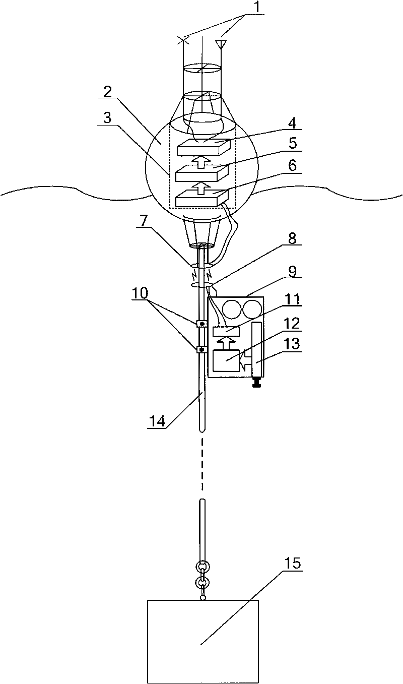
[0047] Such as figure 1 As shown (the curve in the figure is the water surface), the mooring self-elevating profile monitoring buoy based on inductive coupling includes antenna 1, buoy body 2, buoy body instrument compartment 3, communication transceiver module 4, underwater profiler 9, and one-way locking switch 10. Profiler sensor 13, mooring cable 14 and counterweight 15.

[0048] The top of the buoy body 2 is provided with an antenna 1, the bottom of the buoy body 2 is provided with a lower bracket, the bottom of the lower bracket is connected to one end of the mooring cable 14, the other end of the mooring cable 14 is connected to the counterweight 15, and the mooring cable 14 A one-way locking device 10 is arranged on the top, and the one-way locking device 10 is fixedly arranged with the side wall of the underwater profiler 9, and the profiler sensor 13 is arra...


PUM


Abstract

The invention relates to an inductive coupling-based anchoring self-lifting profile monitoring buoy. The conventional monitoring buoy has various deficiencies on communication. The top of a buoy body is provided with an antenna, and the bottom of the buoy body is connected with a counterweight block through a lower bracket and a mooring cable; a buoy body instrument cabin is arranged in the buoy body; a communication transceiving module, a buoy data forwarding module and a coupling signal receiving module are arranged in the buoy body instrument cabin; the communication transceiving module is in signal connection with the buoy data forwarding module; the coupling signal receiving module is in signal connection with the buoy data forwarding module; a coupling signal receiving coil and a coupling signal transmitting coil are sleeved on the mooring cable; the coupling signal receiving coil is in signal connection with a coupling signal transmitting module; the coupling signal transmitting module is in signal connection with an underwater data acquisition and storage module; and the underwater data acquisition and storage module is in signal connection with a profiler sensor. The anchoring self-lifting profile monitoring buoy can realize close-range non-contact wireless transmission in a larger space angle range, and has the advantages of low cost and low power consumption.

Description

technical field [0001] The invention belongs to the technical field of underwater wireless communication, and in particular relates to a mooring self-elevating profile monitoring buoy based on inductive coupling. Background technique [0002] The mooring self-elevating profile monitoring buoy has both the long-term fixed-point characteristics of the mooring buoy and the automatic lifting characteristics of the drifting profile monitoring buoy, and can obtain fixed-point, long-term, high vertical resolution serial vertical profile monitoring data in specific research sea areas. An advanced marine monitoring buoy developed in recent years. This type of buoy usually adopts a two-point mooring design, that is, the upper end is pulled by the buoy, and the lower end is anchored. The profiler moves back and forth between the buoy and the anchorage to collect profile monitoring data. The monitoring data obtained by the profiler is obtained by a certain communication method. After b...

Claims


Application Information

Patent Timeline
IPC IPC(8): G01C13/00G08C17/02B63B22/24
Inventor 于海滨刘敬彪蔡文郁孔庆鹏顾梅园翁杰
Owner HANGZHOU DIANZI UNIV
Learn More