Optical information reproducing apparatus, optical information recording and reproducing apparatus

A reproducing device and information recording technology, applied in the direction of optical recording/reproducing, optical recording head, beam guiding device, etc., can solve the problems of no record and hint, waste of signal recording area, unfavorable low price of recording media, etc. , to achieve the effect of reducing the exposure area

Inactive Publication Date: 2013-03-13
HITACHI CONSUMER ELECTRONICS CORP
View PDF3 Cites 0 Cited by
  • Summary
  • Abstract
  • Description
  • Claims
  • Application Information

AI Technical Summary

Problems solved by technology

[0016] However, as mentioned above, when the beam diameter of the reference light is fixed at the above-mentioned maximum value, it is necessary to irradiate a larger beam diameter in the case of a reference light incident angle at which a smaller beam diameter sufficiently overlaps with the signal light. The reference light, therefore, in the recording medium, such as image 3 As shown, there are many exposure areas that are useless for signal recording
[0017] The generation of this useless exposure area wastes the area used for signal recording, so it is not conducive to large-capacity, high-density recording
In addition, considering the generation of useless exposure areas, if a recording medium with higher performance is used, the specification of the recording medium has to be made stricter, and as a result, it is not conducive to lowering the price of the recording medium.
[0018] In addition, neither of Patent Documents 2 and 3 describes or suggests the above-mentioned related problems.

Method used


Image

  • Optical information reproducing apparatus, optical information recording and reproducing apparatus
  • Optical information reproducing apparatus, optical information recording and reproducing apparatus
  • Optical information reproducing apparatus, optical information recording and reproducing apparatus

Examples


Embodiment 1

[0083] Figure 4 An embodiment of the optical pickup device of the present invention is shown.

[0084] The light beam emitted from the light source 101 passes through the collimator lens 102 and enters the shutter 103 . When the shutter 103 is opened, after the light beam passes through the shutter 103, the direction of polarization is controlled by, for example, an optical element 104 made of a 1 / 2 wavelength plate, so that the light quantity ratio of P polarized light and S polarized light becomes a desired ratio, and then enters to a PBS (Polarization BeamSplitter: Polarization BeamSplitter) prism 105 .

[0085] The light beam passing through the PBS prism 105 is incident on the spatial light modulator 108 through the phase mask 111 , the relay lens 110 , and the PBS prism 107 after being expanded by the beam expander 109 .

[0086] The signal beam to which information is added by the spatial light modulator 108 passes through the PBS prism 107 and propagates through the...

Embodiment 2

[0092] Image 6 Shows the overall configuration of an optical information recording and reproducing device for recording and / or reproducing digital information using holography.

[0093] The optical information recording and reproducing apparatus includes, for example, Figure 4 The optical pickup device 60, the phase conjugate optical system 12, the optical disc curing optical system 13, the optical disc rotation angle detection optical system 14, and the rotary motor 70 of the shown configuration, and the optical information recording medium 100 are rotatable by the rotary motor 70. constitute.

[0094] The optical pickup device 60 emits reference light and signal light to the optical information recording medium 100 to record digital information by using holography.

[0095] At this time, the recorded information signal is sent to the spatial light modulator in the optical pickup device 60 via the signal generating circuit 86 through the actuator 89, and the signal light ...

Embodiment 3

[0108] The optical pickup device of the present invention, such as Figure 5 As shown, the size of the aperture 200 for the reference light can be controlled, and, as Figure 7 As shown, a mechanism capable of controlling the position of the opening 200 may also be provided.

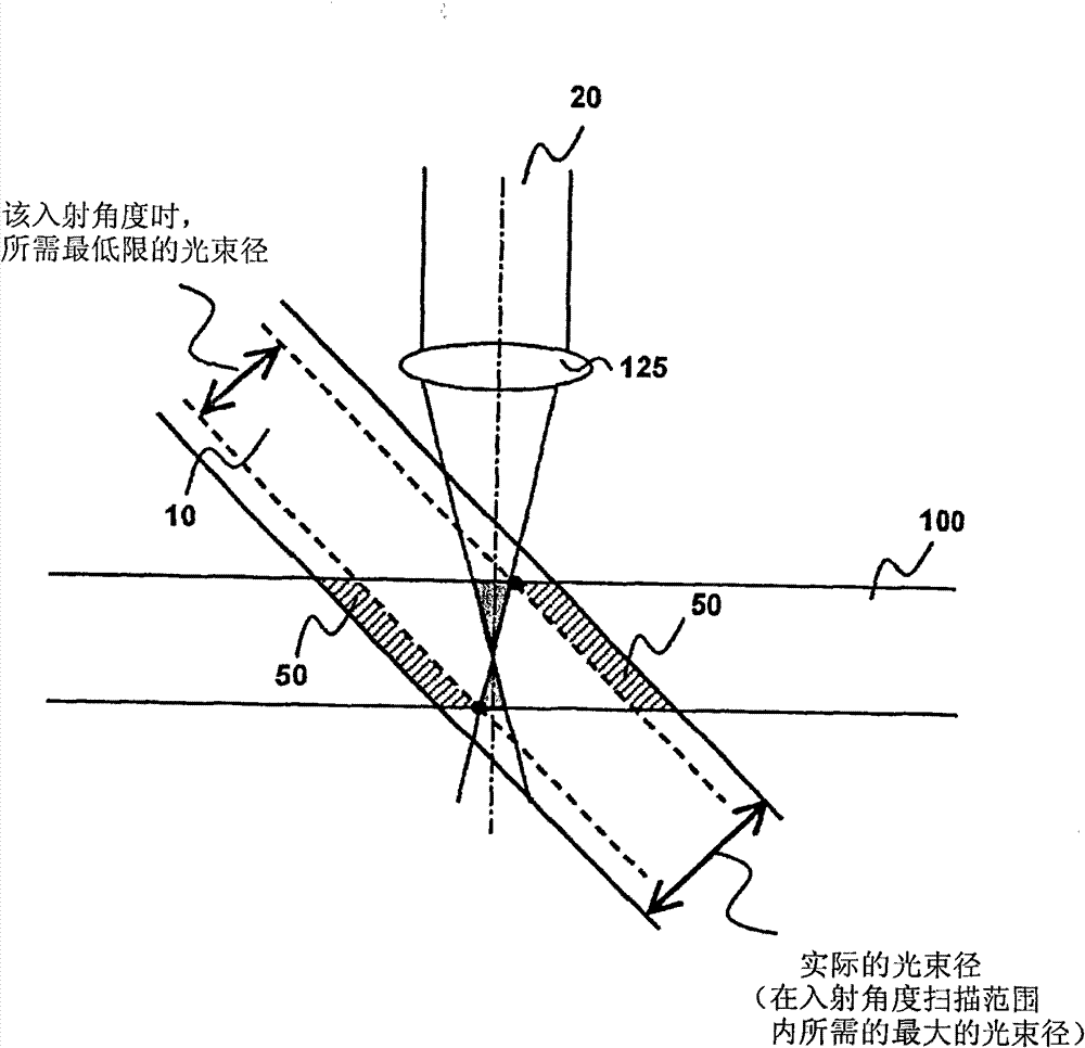
[0109] For example, even in an optical pickup device incorporating high-precision components, various optical components in the optical pickup device may deviate from their initial positions over time due to environmental changes such as temperature and humidity. Thus, if Figure 7 As shown in (a), the irradiation position of the reference light deviates, and as a result, a region where the signal light and the reference light do not overlap often occurs. To avoid this state, as in Figure 7 As shown in (b), it is also possible to sufficiently cover the signal light with the reference light by increasing the size of the aperture, but in this state, useless exposure regions 50 are generated.

[0110] ...


PUM


Abstract

In holographic recording by the angle multiplexing method, in order to allow a signal beam and a reference beam to sufficiently overlap with each other in a storage medium to decrease as much as possible a wastefully exposed region, which does not contribute to a signal recording, an optical pickup apparatus having a function which can control, for example, a size or a position of an aperture of the reference beam is used. An optical information reproducing apparatus or an optical information recording and reproducing apparatus using the optical pickup apparatus is used.

Description

technical field [0001] The present invention relates to a device for recording information on and / or reproducing information from an optical information recording medium using holography. Background technique [0002] Conventionally, an optical disc having a recording density of about 50 GB has been commercialized for consumer use in accordance with the Blu-ray Disc (BD) standard or the like using a blue semiconductor laser. In the future, it is expected that the capacity of optical discs will also increase to the same extent as the capacity of hard disks (HDD: Hard Disc Drive) such as 100 GB to 1 TB. [0003] However, in order to realize such an ultra-high density on an optical disc, a new storage technology is required that is different from the current high-density technical direction of shortening the wavelength and increasing the NA of the objective lens. [0004] The next-generation storage technology is being researched, and hologram recording technology, which uses ...

Claims


Application Information

Patent Timeline
Patent Type & Authority Patents(China)
IPC IPC(8): G11B7/0065G03H1/00
CPCG11B7/0065G11B7/08564G11B7/00772G11B7/139G11B7/1353
Inventor 嶋田坚一
Owner HITACHI CONSUMER ELECTRONICS CORP
Why Eureka
Try Eureka