Automatic press fit sealed large-size workpiece resistance-heated furnace

A resistance heating, enclosed technology, applied in electric furnace heating, lighting and heating equipment, furnaces, etc., can solve the problems of ineffective and fast operation of workpieces, cumbersome process of sealing or opening resistance heating furnaces, large space, etc., to save longitudinal Space, conducive to production safety, the effect of reducing the open area

Inactive Publication Date: 2017-01-11
安庆牛力模具股份有限公司
View PDF3 Cites 0 Cited by
  • Summary
  • Abstract
  • Description
  • Claims
  • Application Information

AI Technical Summary

Problems solved by technology

[0006] The object of the present invention is to provide an automatic press-fit closed large-size workpiece resistance heating furnace, which has the advantages of flexible feeding and discharging and small space occupation, and solves the problem that the existing equipment requires large space for processing large long-axis parts. Inability to operate workpieces efficiently and quickly, and the tedious process of sealing or opening the doors at various openings of the resistance heating furnace

Method used


Image

  • Automatic press fit sealed large-size workpiece resistance-heated furnace
  • Automatic press fit sealed large-size workpiece resistance-heated furnace
  • Automatic press fit sealed large-size workpiece resistance-heated furnace

Examples


Embodiment Construction

[0022] The following will clearly and completely describe the technical solutions in the embodiments of the present invention with reference to the accompanying drawings in the embodiments of the present invention. Obviously, the described embodiments are only some, not all, embodiments of the present invention. Based on the embodiments of the present invention, all other embodiments obtained by persons of ordinary skill in the art without making creative efforts belong to the protection scope of the present invention.

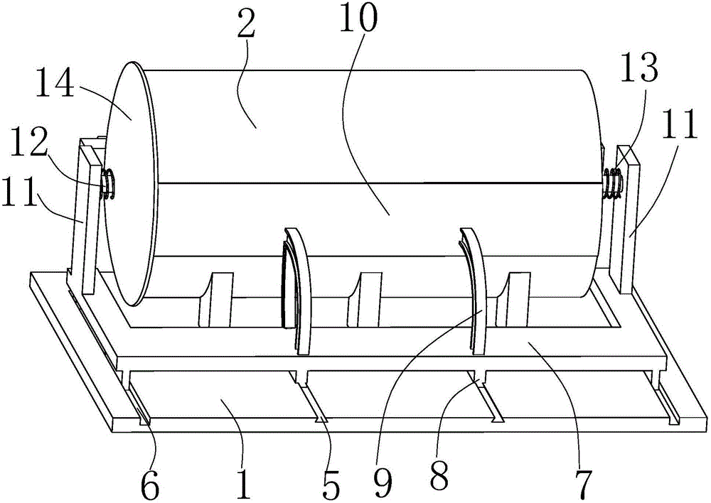
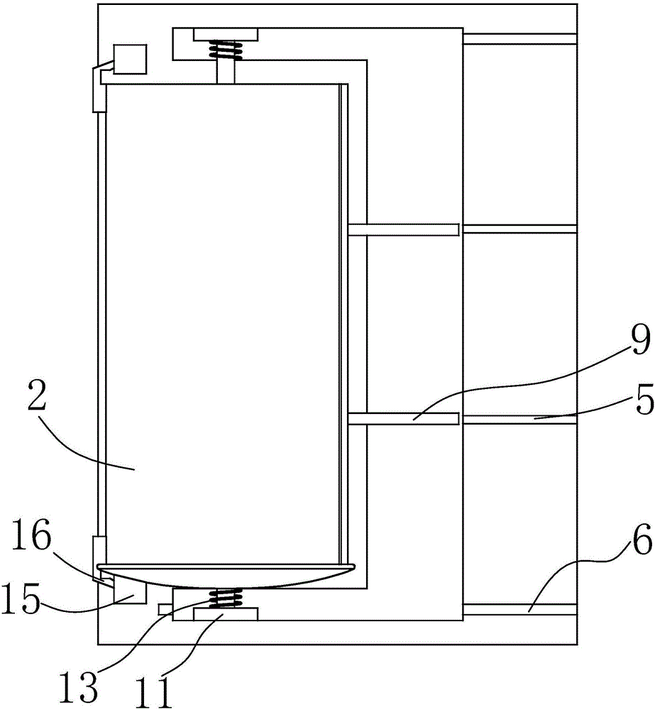
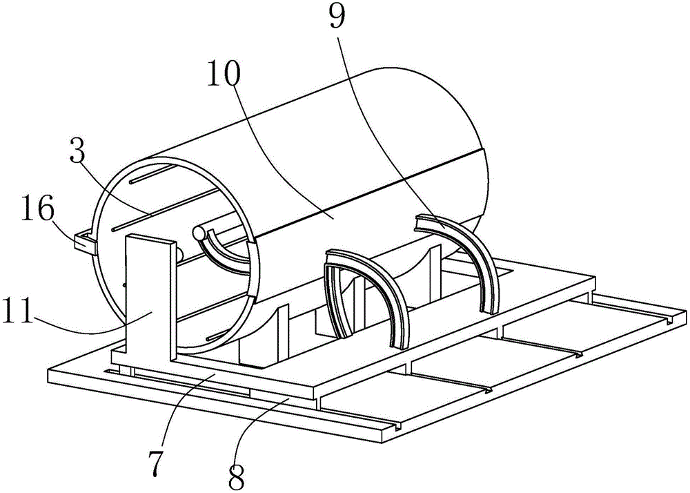
[0023] see Figure 1-4 , an automatic press-fit closed large-size workpiece resistance heating furnace, including a bottom plate 1, a resistance heating furnace 2 is fixed on the left side of the bottom plate 1, and a layer is evenly attached to the inner wall of the resistance heating furnace 2 for blocking heat asbestos, on which several resistance wires 3 are evenly fixed.

[0024] The right side of the resistance heating furnace 2 is provided with a feed ...


PUM


Abstract

The invention discloses an automatic press fit sealed large-size workpiece resistance-heated furnace which comprises a bottom plate. A resistance-heated furnace body is fixed to the left side of the bottom plate, a layer is asbestos is evenly attached to the inner wall of the resistance-heated furnace body, a plurality of resistance wires are evenly fixed to the asbestos, and a feeding window arranged in the length direction of the resistance-heated furnace body is arranged on the right side face of the resistance-heated furnace body. Two first sliding channels exactly located on the right side of the resistance-heated furnace body are arranged on the right side of the upper end face of the bottom plate, second sliding channels correspondingly located on the front side and the rear side of the resistance-heated furnace body are arranged on the front side and the rear side of the upper end face of the bottom plate correspondingly, and a propelling plate is arranged on the right side of the bottom plate. The feeding window is creatively formed in the side wall of the resistance-heated furnace body, on the one hand, the area of an opening of the resistance-heated furnace body is reduced, it can be guaranteed that the area, for fixing the resistance heating wires, in the resistance-heated furnace body is maximized, and meanwhile production safety is promoted; and on the other hand, the resistance-heated furnace is suitable for taking and placing of long shaft parts, and the longitudinal space of a plant is saved.

Description

technical field [0001] The invention relates to the technical field of resistance heating furnace equipment, in particular to an automatic pressing closed resistance heating furnace for large-sized workpieces. Background technique [0002] Resistance heating furnace is an industrial furnace that uses electric current to heat the electric heating element or heating medium in the furnace, thereby heating the workpiece or material. Resistance heating furnaces are used in the machinery industry for heating before metal forging, metal heat treatment, brazing, powder metallurgy sintering, glass ceramics firing and annealing, melting of low melting point metals, drying of sand molds and paint films, etc. [0003] The existing resistance heating furnace is usually a rectangular box, with a movable door on one side, and the other side is closed, put the workpiece into the box, use the control system connected to the box to detect the temperature in the box, and conduct electricity h...

Claims


Application Information

Patent Timeline
Patent Type & Authority Applications(China)
IPC IPC(8): F27B17/00F27D3/00F27D11/02
CPCF27B17/0016F27D3/0084F27D11/02
Inventor 严冬祥
Owner 安庆牛力模具股份有限公司
Why Eureka
Try Eureka