Photographic hologram system

a technology of optical holograms and holograms, applied in the field of optical hologram systems, can solve the problems of the plurality of interference fringes of two-dimensional area on the film, and achieve the effects of reducing the exposure regions of interference fringes, enhancing the brightness of the reconstructed image, and reducing the times of multiple exposures of the film

Inactive Publication Date: 2014-08-26
E LON OPTRONICS
View PDF1 Cites 0 Cited by
  • Summary
  • Abstract
  • Description
  • Claims
  • Application Information

AI Technical Summary

Benefits of technology

[0007]The present invention provides a photographic hologram system for use in a reflection-type color photographic hologram system or a transmission-type color photographic hologram system. A half-cylindrical lens and a lens set of an object beam processing unit are collectively used, wherein the half-cylindrical lens is arranged in the optical path of the object beam and upstream of the film. The arrangement of the half-cylindrical lens is effective to reduce the exposure regions of the interference fringes of the film, which are generated by the object beam and the reference beam. Consequently, the times of multiple exposures of the film are reduced, and the brightness of the reconstructed image is enhanced. In addition, the photographic hologram system can be employed to produce large-sized holograms.
[0008]The present invention further provides a photographic hologram system by slicing pixels from the image. In such way, the pixel values of two image frames of a target object are reduced and complementary to each other. The image slicing process is effective to reduce the exposure regions of the interference fringes of the film, which are generated by the object beam and the reference beam. Consequently, the times of multiple exposures of the film are reduced, and the brightness of the reconstructed image is enhanced. In addition, the photographic hologram system can be employed to produce large-sized holograms.
[0009]The present invention still provides a photographic hologram system for producing a reference beam carrying the image information of a target object, thereby reducing the exposure regions of the interference fringes of the film, which are generated by the object beam and the reference beam. Consequently, the times of multiple exposures of the film are reduced, and the brightness of the reconstructed image is enhanced. In addition, the photographic hologram system can be employed to produce large-sized holograms.

Problems solved by technology

When the reference light wave and the object light wave are incident to the film, the reference light wave and the object light wave are interfered with each other to result in a plurality of interference fringes of two-dimensional area on the film.

Method used


Image

  • Photographic hologram system
  • Photographic hologram system
  • Photographic hologram system

Examples


first embodiment

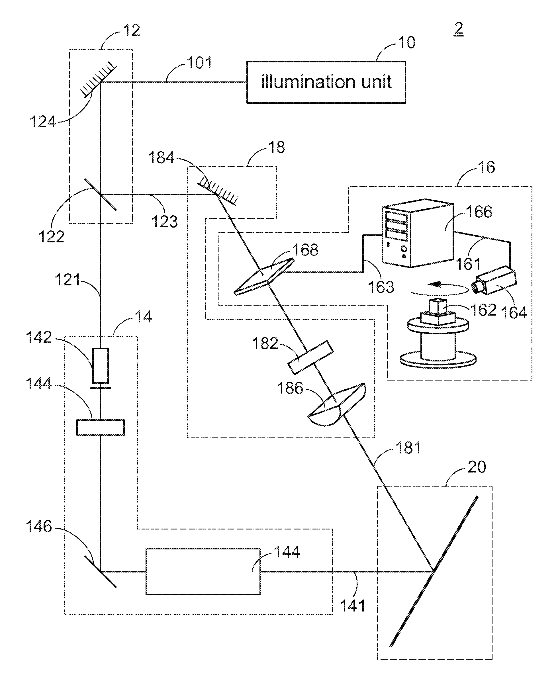
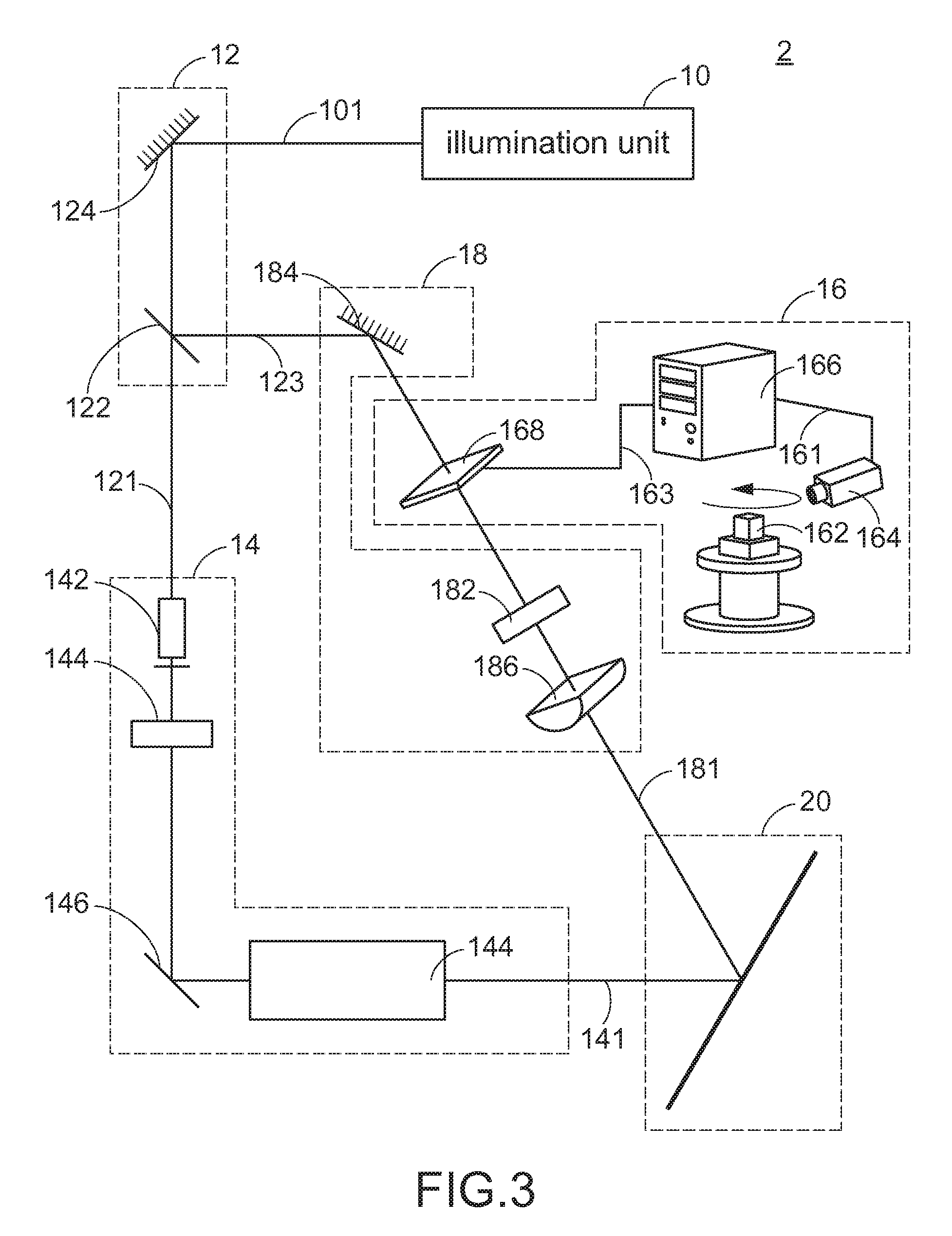
[0036]FIG. 3 schematically illustrates the architecture of a photographic hologram system according to the present invention. As shown in FIG. 3, the photographic hologram system 2 comprises an illumination unit 10, a beam splitting unit 12, a reference beam processing unit 14, an image generating unit 16, an object beam processing unit 18, and a film 20.

[0037]The illumination unit 10 is used for providing a coherent beam 101. For example, the illumination unit 10 may be any kind of laser beam generator for emitting a coherent laser beam 101. Dependent on the medium of the laser beam generator, the laser beam generator includes for example a gas laser beam generator (e.g. a helium-neon laser beam generator), a carbon dioxide laser beam generator, a liquid laser beam generator, a solid laser beam generator, or a semiconductor laser beam generator. Depending on the wavelength of the laser beam, the laser beam may be a visible laser beam or an invisible laser beam.

[0038]After the coher...

second embodiment

[0052]FIG. 8 schematically illustrates the architecture of a photographic hologram system according to the present invention. The photographic hologram system 4 is capable of performing a color separating operation on the image 161 of a colorful target object 162. Consequently, various color pixels of the image 161 are separated, and respective color pixels are combined as a first monochromatic component image and a second monochromatic component image. The first monochromatic color of the first monochromatic component image is different from the second monochromatic color of the second monochromatic component image. For example, the image may be separated into a red color two-dimensional image, a green color two-dimensional image and a blue color two-dimensional image, which are respectively served as the first monochromatic component image, the second monochromatic component image and the third monochromatic component image.

[0053]For the colorful target object 162, the object beam...


PUM


Abstract

A photographic hologram system is provided. The use of an image slicing process and / or the arrangement of half-cylindrical lens in the optical path of an optical light wave and upstream of the film is effective to reduce the times of multiple exposures of the film. As a consequence, the brightness of the reconstructed image is enhanced.

Description

FIELD OF THE INVENTION[0001]The present invention relates to a system for forming a hologram, and more particularly to a system for forming an optical hologram.BACKGROUND OF THE INVENTION[0002]In a conventional optical holographic technology, a portion of a coherent beam is used to irradiate to an object, and the reflected light from the object or the light transmitted through the object is incident to a holographic plate. This light is called as an object beam. Another portion of the coherent beam is projected onto the holographic plate to be used as a reference beam. Since the object beam and the reference beam are from the same coherent beam, the object beam and the reference beam are interfered with each other at the holographic plate to result in many bright and dark interference fringes. The interference pattern recorded on the holographic plate is formed as a hologram. The shape of the interference pattern indicates the phase relationship between the object beam and the refer...

Claims


Application Information

Patent Timeline
Patent Type & Authority Patents(United States)
IPC IPC(8): G03H1/08G03H1/00G03H1/28
CPCG03H1/268G03H2001/2685G03H2001/2695G03H2210/42G03H2210/441
Inventor YAO, MING, TANG
Owner E LON OPTRONICS
Why Eureka
Try Eureka