
Energy-saving lamp using high-power spiral energy-saving lamp tube

An energy-saving lamp and high-power technology, which is applied to parts of gas discharge lamps, discharge lamps, discharge tubes, etc., can solve problems such as difficulty in meeting large-scale production, increasing manufacturing difficulty, and heating and bending of long glass tubes. Achieve the effect of satisfying large-scale production, improving reliability and simple manufacturing process

Inactive Publication Date: 2012-05-30
ZHEJIANG YANKON GROUP
View PDF0 Cites 0 Cited by
  • Summary
  • Abstract
  • Description
  • Claims
  • Application Information

AI Technical Summary

Problems solved by technology

The energy-saving lamps used in these high-power spiral energy-saving lamps are high-power double-helix energy-saving lamps. This type of double-helix energy-saving lamps usually achieves the purpose of increasing power by lengthening the length of the lamp. However, the length of the lamp The longer the tube voltage is, the higher the tube voltage will be. If the tube voltage is too high, it will be difficult to guarantee the reliability of the drive matching between the ballast and the lamp; Tube and large-scale heating bending forming process, which increases the difficulty of production and is difficult to meet the requirements of large-scale production; in addition, because the tube wall temperature of high-power double-helix energy-saving lamp tubes is relatively high, if only conventional methods such as using The top of the lamp tube protrudes slightly as a cold end manufacturing process, which has been difficult to fully realize the purpose of controlling the temperature of the cold end, thus affecting the light efficiency of the high-power lamp tube

Method used


Image

  • Energy-saving lamp using high-power spiral energy-saving lamp tube
  • Energy-saving lamp using high-power spiral energy-saving lamp tube
  • Energy-saving lamp using high-power spiral energy-saving lamp tube

Examples


Embodiment Construction

[0030] The present invention will be further described in detail below in conjunction with the accompanying drawings and embodiments.

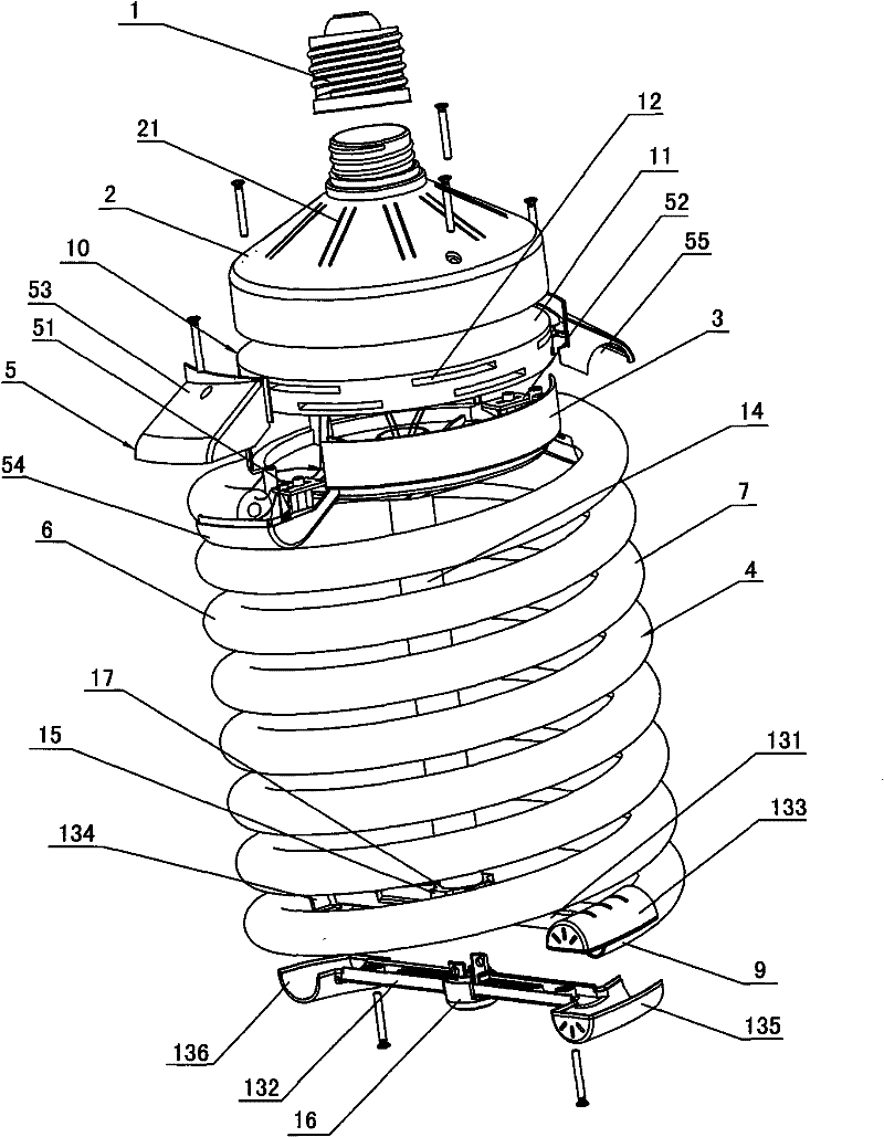
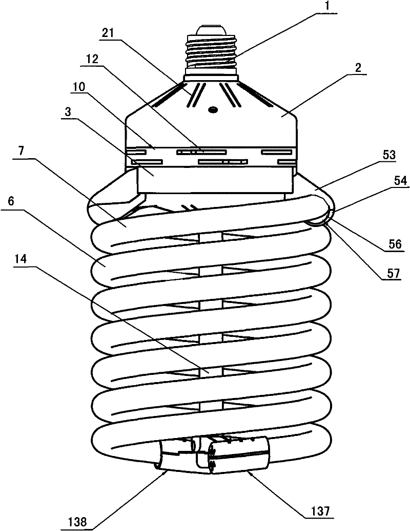
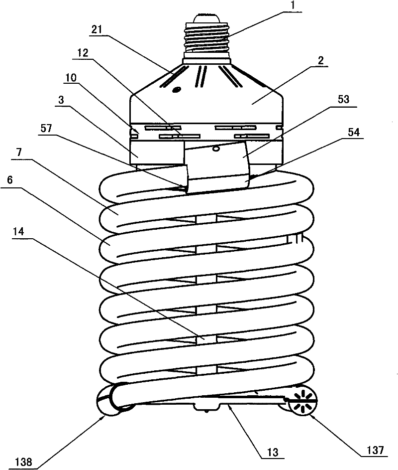
[0031] As shown in the figure, an energy-saving lamp using a high-power spiral energy-saving lamp tube includes a lamp cap 1, an upper cover 2, a lower cover 3, a ballast (not shown in the figure) and a double-helix energy-saving lamp tube 4, and the upper cover The upper end of 2 is connected with the lamp holder 1, and the upper cover 2 is connected with the lower cover 3 through existing fasteners such as screws. Matching oblique interface 5 . Here, the double-helix energy-saving lamp tube 4 used includes two first single-helix lamp tubes 6 and second single-helix lamp tubes 7 with the same structure and both cylindrical shapes. Figure 8 and Figure 9 The structure of the single helical lamp is given ( Figure 8 and Figure 9 marked with the first single helical lamp), the helical direction of the first single helical lamp 6 and the se...


PUM


Abstract

The invention discloses an energy-saving lamp using a high-power spiral energy-saving lamp tube. The double spiral energy-saving lamp tube of the energy-saving lamp is composed of two single spiral lamp tubes in the same structure, wherein one single spiral lamp tube spirals in the same direction to enter the other single spiral lamp tube; and since the two single spiral lamp tubes work independently, as for the driving circuit, the length of the double single spiral lamp tube is reduced by one half as compared with the length of the prior double single spiral lamp tube, thereby easily matching the driving circuit and enhancing the drive matching reliability between the ballast and the lamp tube. Meanwhile, since the double spiral energy-saving lamp tube in the structure is composed of the two single spiral lamp tubes, and the manufacture of the single spiral lamp tube does not need a long glass tube, the manufacture technology is simple and can well satisfy the requirements for large-scale production of high-power spiral lamp tubes. The lighting effect of the energy-saving lamp in the structure can reach above 801 m / W; and when the diameter of the single spiral lamp tube is 14-22mm, the power range of the energy-saving lamp is 100-250 W.

Description

technical field [0001] The invention relates to an energy-saving lamp, in particular to an energy-saving lamp using a high-power spiral energy-saving lamp tube. Background technique [0002] With the improvement of lighting quality, the most scientific way to save lighting costs is to effectively use energy-saving lamps. Energy-saving lamps have many advantages such as energy saving, high luminous efficiency, long life, environmental protection, good color rendering, and compact structure. They are more and more widely used and more and more types. Spiral energy-saving lamps are a common type of energy-saving lamps. Among them, high-power spiral energy-saving lamps have been widely used in the field of lighting due to their advantages in high efficiency and energy saving, especially for large-area indoor and outdoor lighting. A high-power spiral energy-saving lamp usually includes a lamp cap, an upper cover, a lower cover, a ballast and an energy-saving lamp tube. The balla...

Claims


Application Information

Patent Timeline
Patent Type & Authority Patents(China)
IPC IPC(8): H01J61/32H01J61/24H01J5/50
Inventor 李阳
Owner ZHEJIANG YANKON GROUP
Learn More