Magnetic suspension inching platform with six degrees of freedom
A micro-movement platform and magnetic levitation technology, which is applied to the holding device and electrical components using magnetic attraction or thrust, can solve the problems of low positioning accuracy, low thrust density, and large loss, and achieve high positioning accuracy, easy control, and structure. simple effect
- Summary
- Abstract
- Description
- Claims
- Application Information
AI Technical Summary
Problems solved by technology
Method used
Image

Examples
Example Embodiment
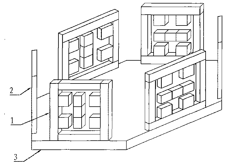
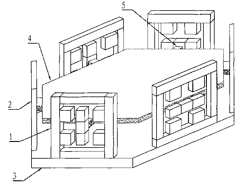
[0009] Specific embodiment 1: The six-degree-of-freedom magnetic levitation micro-motion platform described in this embodiment includes a platform base, a support platform 4, m magnetic levitation horizontal support mechanisms 1 and m magnetic levitation vertical support mechanisms 2, m magnetic levitation horizontal support mechanisms 1 and m magnetic levitation vertical support mechanisms 2 are fixed on the periphery of the top surface of the platform base and form a symmetrical structure of 2m polygons. The support platform 4 and each magnetic levitation horizontal support mechanism 1 mover 11 and m magnetic levitation vertical supports The mover 21 of the mechanism 2 is fixedly connected, the magnetic levitation vertical support mechanism 2 has the same structure as the magnetic levitation horizontal support mechanism 1, the movement direction of the mover 21 of the magnetic levitation vertical support mechanism 2 is the vertical direction, and the magnetic levitation horizon...
Example Embodiment
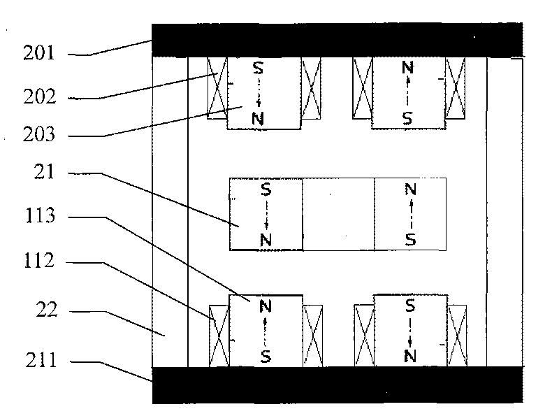
[0012] Specific implementation manner 2: see Figure 7 This embodiment will be described. The difference between this embodiment and the six-degree-of-freedom magnetic levitation micro-motion platform described in the first embodiment is that the maglev horizontal support mechanism 1 is composed of a stator and a mover 11. The stator includes a left yoke plate 101 and a left yoke plate permanent magnet assembly 103. Left control coil group 102, two supporting edges 12, right yoke plate 111, right yoke plate permanent magnet group 113, right control coil group 112, left yoke plate 101 and right yoke plate 111 are arranged parallel to each other, left yoke plate 101 The right yoke plate 111 and the two supporting edges 12 form a rectangular frame. The left yoke plate permanent magnet group 103 is fixed on the right surface of the left yoke plate 101, and the right yoke plate permanent magnet group 113 is fixed on the left surface of the right yoke plate 111. The left yoke plate p...
Example Embodiment
[0013] Specific implementation manner three: see Figure 8 This embodiment will be described. The difference between this embodiment and the six-degree-of-freedom magnetic levitation micro-motion platform described in the first embodiment is that the maglev horizontal support mechanism 1 is composed of a stator and a mover 11. The stator includes a left yoke plate 101 and a left yoke plate permanent magnet assembly 103. Left control coil group 102, two supporting edges 12, right yoke plate 111, right yoke plate permanent magnet group 113, right control coil group 112, left yoke plate 101 and right yoke plate 111 are arranged parallel to each other, left yoke plate 101 The right yoke plate 111 and the two supporting edges 12 form a rectangular frame. The left yoke plate permanent magnet group 103 is fixed on the right surface of the left yoke plate 101, and the right yoke plate permanent magnet group 113 is fixed on the left surface of the right yoke plate 111. The left yoke pl...
PUM
 Abstract
Description
Claims
Application Information
 - R&D Engineer
- R&D Manager
- IP Professional
- Industry Leading Data Capabilities
- Powerful AI technology
- Patent DNA Extraction
Browse by: Latest US Patents, China's latest patents, Technical Efficacy Thesaurus, Application Domain, Technology Topic.
© 2024 PatSnap. All rights reserved.Legal|Privacy policy|Modern Slavery Act Transparency Statement|Sitemap