Power factor correction converter including input current detecting circuit

a converter and input current technology, applied in the direction of electric variable regulation, process and machine control, instruments, etc., can solve the problems of loss of power consumption in the current detecting resistor itself, increase the overall cost of the sensor, etc., and achieve accurate detection of inductor current, appropriate correction of power factor, low loss

Active Publication Date: 2013-03-12
MURATA MFG CO LTD
View PDF27 Cites 121 Cited by
  • Summary
  • Abstract
  • Description
  • Claims
  • Application Information

AI Technical Summary

Benefits of technology

[0025]To overcome the problems described above, preferred embodiments of the present invention provide a low-cost PFC converter that accurately detects an inductor current including a DC component and appropriately corrects a power factor with low loss.
[0048]In the PFC converter according to various preferred embodiments of the present invention, the cost is significantly reduced by using a current detecting resistor. In addition, since the current detecting resistor is used, an inductor current including a DC component can be detected, and a power factor can be appropriately corrected. Further, a current flows through the current detecting resistor only during any of the on period and off period of the switching element, and thus, the power loss caused by the current detecting resistor is reduced. Furthermore, when using a current transformer for current detection, only one current transformer is required and, thus, the cost and size are reduced. Furthermore, lower loss and simplification of the current detecting circuit are achieved.

Problems solved by technology

In the above-described method (1) of using a current detecting resistor, power consumption in the current detecting resistor itself is loss, which is a problem in terms of reducing loss.
In the method (3) of using a hole sensor, the problems that may occur in the methods (1) and (2) do not arise, but the overall cost increases because the sensor is expensive.

Method used


Image

  • Power factor correction converter including input current detecting circuit
  • Power factor correction converter including input current detecting circuit
  • Power factor correction converter including input current detecting circuit

Examples


first preferred embodiment

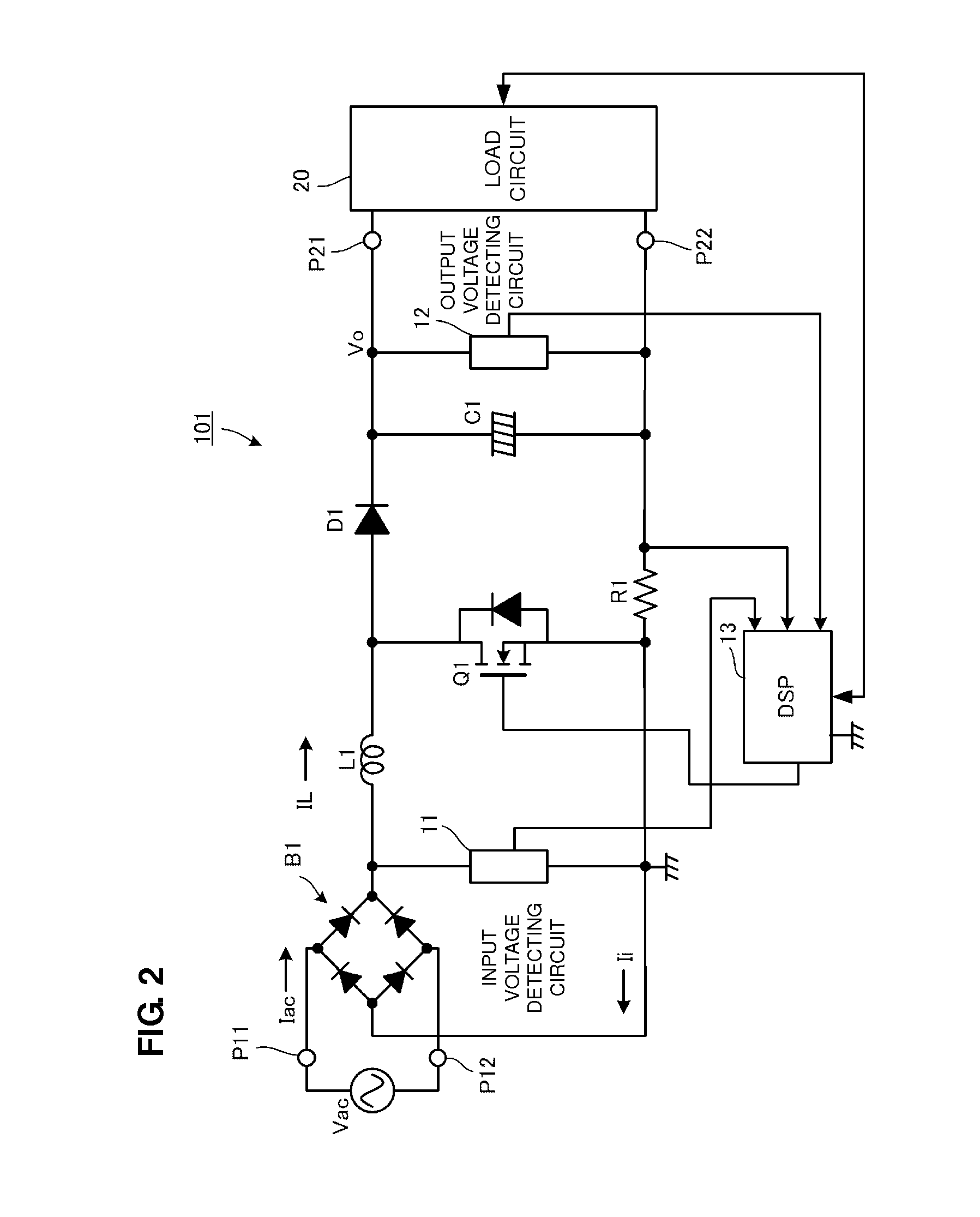
[0065]A PFC converter according to a first preferred embodiment of the present invention will be described with reference to FIGS. 2 to 4.

[0066]FIG. 2 is a circuit diagram of the PFC converter according to the first preferred embodiment. In FIG. 2, symbols P11 and P12 denote input ports of the PFC converter 101, and symbols P21 and P22 denote output ports of the PFC converter 101. An AC input power supply Vac, which is a commercial AC power supply, is input to the input ports P11 and P12, and a load circuit 20 is connected to the output ports P21 and P22.

[0067]The load circuit 20 is, for example, a circuit of a DC-DC converter and an electronic apparatus that is supplied with power by the DC-DC converter.

[0068]In an input stage of the PFC converter 101, a diode bridge B1 that performs full-wave rectification on an AC voltage of the AC input power supply Vac is preferably provided. On the output side of the diode bridge B1, a series circuit including an inductor L1, a switching eleme...

second preferred embodiment

[0082]FIG. 6 is a circuit diagram of a switching power supply device 201 according to a second preferred embodiment of the present invention.

[0083]In FIG. 6, the switching power supply device 201 preferably includes a PFC converter 102 and a DC-DC converter 50. A load 60 is connected to the output of the DC-DC-converter 50.

[0084]An AC input power supply Vac, which is a commercial AC power supply, is input to input ports P11 and P12 of the PFC converter 102, and the DC-DC converter 50 is connected to the output portion. The PFC converter 102 preferably includes a diode bridge B1 arranged to perform full-wave rectification on the AC input power supply Vac, an inductor L1 connected to the output of the diode bridge B1, a switching element Q1, a diode D1, and a smoothing capacitor C1. The inductor L1, the switching element Q1, the diode D1, and the smoothing capacitor C1 define a step-up chopper circuit.

[0085]In contrast to the first preferred embodiment illustrated in FIG. 2, in the se...

third preferred embodiment

[0093]FIG. 8 is a circuit diagram of a PFC converter 103 according to a third preferred embodiment of the present invention. FIG. 9 is a waveform diagram of individual portions of the PFC converter 103.

[0094]The PFC converter 103 preferably includes three inductors L11, L12, and L13, three diodes D11, D12, and D13, and three switching elements Q11, Q12 and Q13, thereby defining a three-phase PFC converter. A digital signal processing circuit 13 detects an input voltage using an input voltage detecting circuit 11, receives decreased voltages from current detecting resistors R11, R12, and R13, and supplies switching control signals to the switching elements Q11, Q12, and Q13, respectively.

[0095]FIG. 9 is a waveform diagram of inductor currents IL11, IL12, and IL13 flowing through the three inductors L11, L12, and L13 of the PFC converter 103 illustrated in FIG. 8, and an input current IL. By sequentially turning on / off the three switching elements Q11, Q12, and Q13 with a phase differ...


PUM


Abstract

A low-cost PFC converter capable of detecting an inductor current including a DC component and performing appropriate correction of a power factor with low loss includes a diode bridge that rectifies an AC voltage input from an AC input power supply Vac, a series circuit including an inductor and a switching element, a rectifying and smoothing circuit that is connected in parallel to the switching element and that includes a diode and a smoothing capacitor, and a digital signal processing circuit that performs on / off control on the switching element so that an input current input from the AC input power supply Vac has a similar waveform with respect to an AC voltage. A current flowing through the inductor during an off period of the switching element is detected using a current detecting resistor, and a decreased voltage of the current detecting resistor is sampled at the middle of the off period of the switching element, thereby detecting an average value of the input current.

Description

BACKGROUND OF THE INVENTION[0001]1. Field of the Invention[0002]The present invention relates to an alternating current to direct current (AC-DC) converter that receives an AC power supply and that outputs a DC voltage, and particularly, to a power-factor correction (PFC) converter for correcting a power factor.[0003]2. Description of the Related Art[0004]In Japan and Europe, for example, harmonic current control that is classified in accordance with an application or input power is performed. In order to respond to such control, a circuit called a PFC converter is added to a power supply of general home appliances subjected to harmonic current control, whereby measures have been taken to suppress harmonic currents.[0005]In a typical switching power supply device using a commercial AC power supply as an input power supply, the commercial AC power supply is rectified and smoothed so as to be converted to a DC voltage, and switching by a DC-DC converter is performed on the DC voltage....

Claims


Application Information

Patent Timeline
Patent Type & Authority Patents(United States)
IPC IPC(8): G05F1/00H02M3/335H02M5/45H02M5/458
CPCH02M1/4225H02M2001/0009Y02B70/126Y02B70/10H02M1/0009H02M1/0085
Inventor UNO, YOSHIYUKI
Owner MURATA MFG CO LTD
Why Eureka
Try Eureka